

Smart ground bonding method for facilities
- Summary
- Abstract
- Description
- Claims
- Application Information
AI Technical Summary
Benefits of technology
Problems solved by technology
Method used
Image

Examples
first embodiment
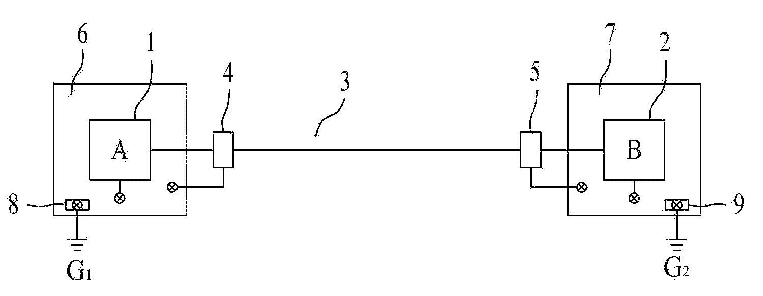
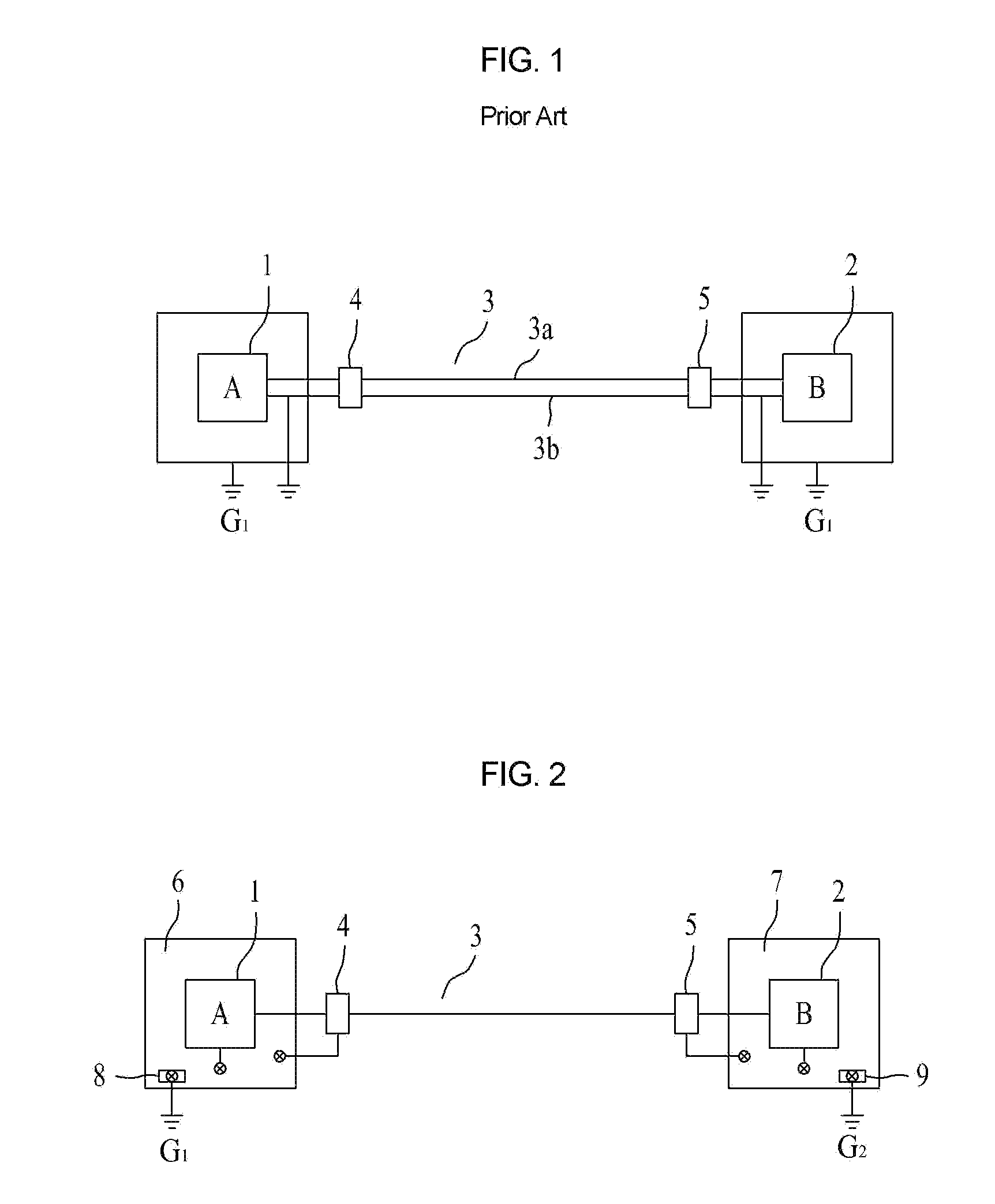
[0040]FIG. 2 illustrates a facility grounding structure according to the present invention.
[0041]As illustrated in FIG. 2, in the facility grounding structure according to the first embodiment of the present invention, an electric wire is connected between a first facility 1 and a second facility 2, a first surge protection device 4 is connected between the first facility 1 and the electric wire 3, a second surge protection device 5 is connected between the electric wire 3 and the second facility 2, and ground terminals of the first and second surge protection devices 4 and 5 are connected to the ground.
[0042]The ground terminals of the first and second surge protection devices 4 and 5 are bonded to metal boxes 6 and 7 of the first and second facilities, and ground terminal blocks 8 and 9 connected to the ground are formed on sides of the metal boxes 6 and 7. Here, the surge protection devices 4 and 5 are bonded to portions in the metal boxes 6 and 7 of the facilities 1 and 2 closes...
second embodiment
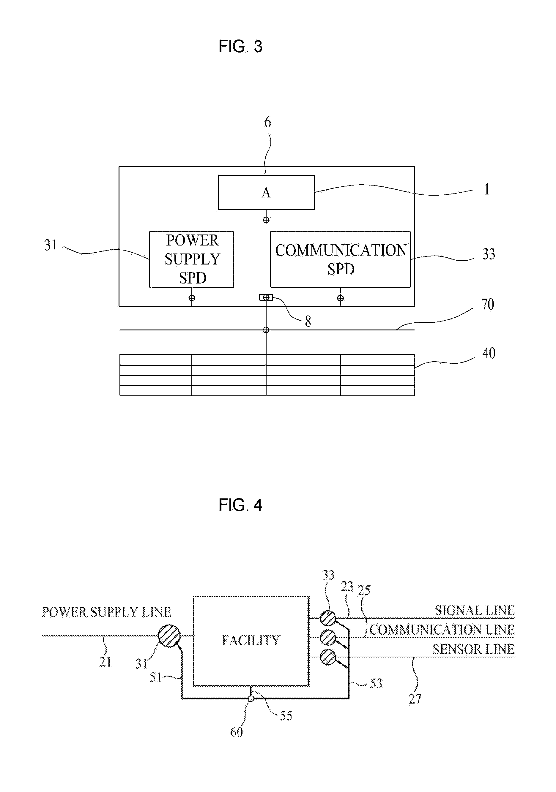
[0046]FIG. 3 is a facility grounding structure according to the present invention.
[0047]The second embodiment of the present invention corresponds to a structure where ground terminals of a power supply surge protection device 31 and a communication surge protection device 33 installed in one facility are bonded to closest portions of a metal box 6 and a ground terminal block 8 formed on one side of the metal box 6 is connected to a mesh ground 40 or is connected to a nearby metal structure when there is no ground or a defective ground.
[0048]Here, it is preferable that the metal structure contacts the earth or is located to face the earth, which is because the metal structure such as a metal pipe or a steel frame of a building is installed in the vicinity of the ground surface, acting as an excellent ground by itself.
[0049]Here, the metal structure includes a water pipe, a water main, a gas pipe, a hot water pipe, a water supply pipe, a water discharge pipe, a wire pipe, a frame, a ...
third embodiment
[0050]FIG. 4 illustrates a facility grounding structure according to the present invention.
[0051]As illustrated in FIG. 4, various lines such as a power supply line 21, a signal line 23, a communication line 25, and a sensor line 27 are connected to a facility of a plant, and a power supply surge protection device 31 is connected to the power supply line 21 and the facility, and a communication surge protection device 33 is connected to communication lines such as the signal line 23, the communication line 25, and the sensor line 27.
[0052]While the power supply surge protection device 31 and the communication surge protection device 33 are conventionally grounded to a mesh ground in a single grounding manner, the ground terminals of the power supply surge protection device 31 and the communication surge protection device 33 are connected to each other to form a common ground terminal 60 and the common ground terminal 60 is connected to a conductive frame (not shown) of the facility ...
PUM
 Abstract
Description
Claims
Application Information