
Distance- and frequency-separated swept-frequency seismic sources

a technology of swept-frequency seismic sources and distance and frequency separation, which is applied in the field of seismic exploration, can solve the problems of difficult to build a single swept-frequency source that covers this entire range, difficult to achieve the necessary control to precisely synchronize the phases of two or more resonators, and inefficient use of this expensive resource. achieve the effect of enhancing simultaneous source separation

Inactive Publication Date: 2012-06-14
BP CORP NORTH AMERICA INC
View PDF14 Cites 94 Cited by
  • Summary
  • Abstract
  • Description
  • Claims
  • Application Information

AI Technical Summary

Benefits of technology

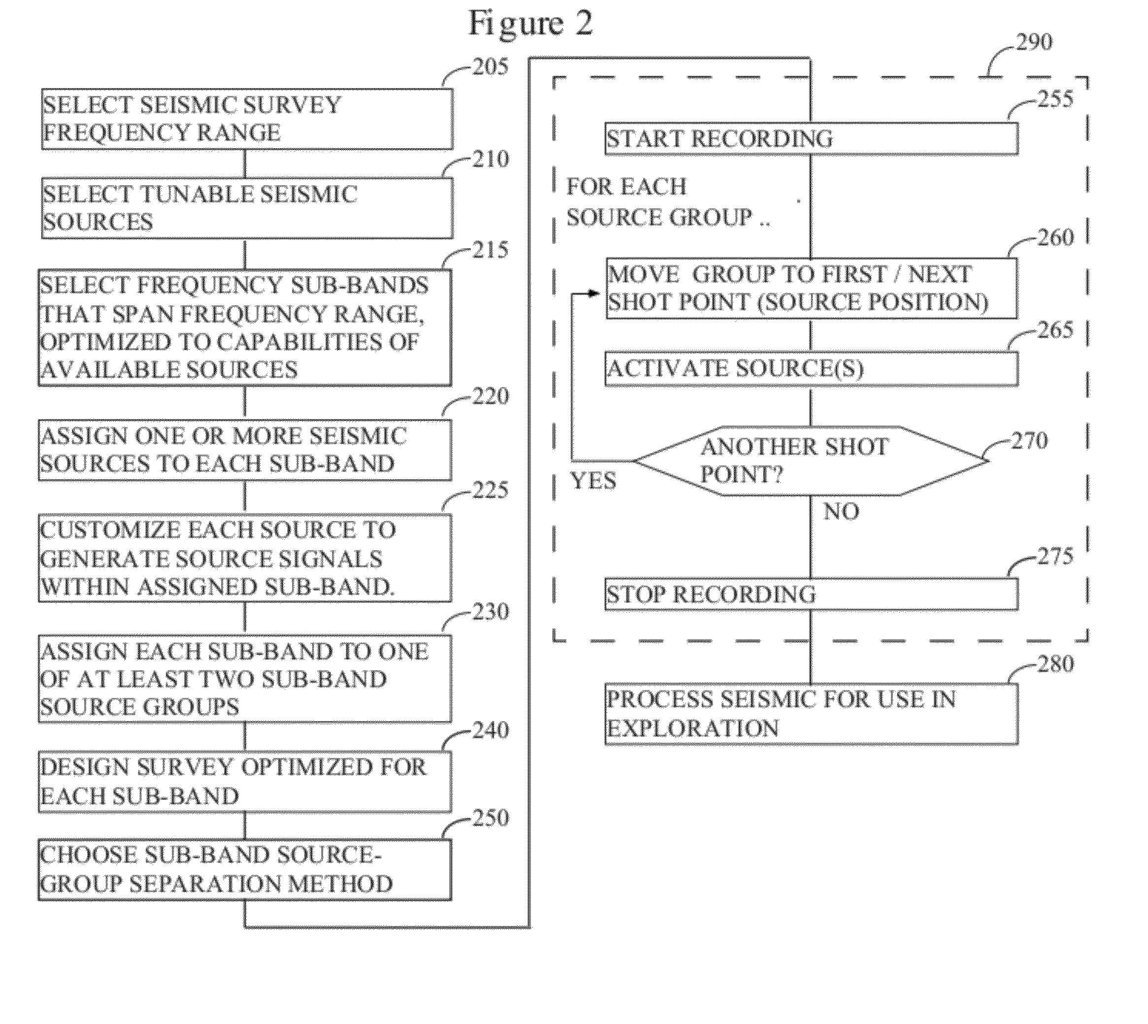
[0017]The bank of sub-band sources will then be divided into two or more groups, such that no sources that are assigned to adjacent frequency sub-bands are placed in the same group. Such a group of sources will be referred to as a “sub-band source group” or just “source group”, hereinafter. The sub-band sources within each sub-band source group can be readily separated in the frequency domain by simple bandpass filtering, allowing each sub-band source to essentially be operated independently (i.e., without regard for what the other sub-band sources are doing). That may mean that the sub-band sources will be activated simultaneously, sequentially, contemporaneously (e.g., two or more of the sources in a group may overlap in time), etc. It would be most efficient for acquisition purposes for all of the sub-band sources in the same source group to be simultaneously active.

Problems solved by technology

However, in practice it is very difficult to build a single swept-frequency source that covers this entire range.
First, for marine resonator sources achieving the necessary control to precisely synchronize the phases of two or more resonators is likely to be difficult.
Second, each individual source then spends most of its time idle when it could be usefully radiating energy, which is not an efficient use of this expensive resource.
However, this proposal again fails to address the first problem discussed above.
However, this approach does not provide a methodology for how to operate the sources such that they can be separated in processing while still covering the entire frequency band of interest.
Finally, none of these methods attempts to take advantage of the fact that different minimum source separations are used in different frequency bands.
It is not possible with airguns, but with swept-frequency sources partitioning a frequency range of interest, it potentially is.

Method used


Image

  • Distance- and frequency-separated swept-frequency seismic sources
  • Distance- and frequency-separated swept-frequency seismic sources
  • Distance- and frequency-separated swept-frequency seismic sources

Examples


Embodiment Construction

[0033]While this invention is susceptible of embodiment in many different forms, there is shown in the drawings, and will herein be described hereinafter in detail, some specific embodiments of the instant invention. It should be understood, however, that the present disclosure is to be considered an exemplification of the principles of the invention and is not intended to limit the invention to the specific embodiments or algorithms so described.

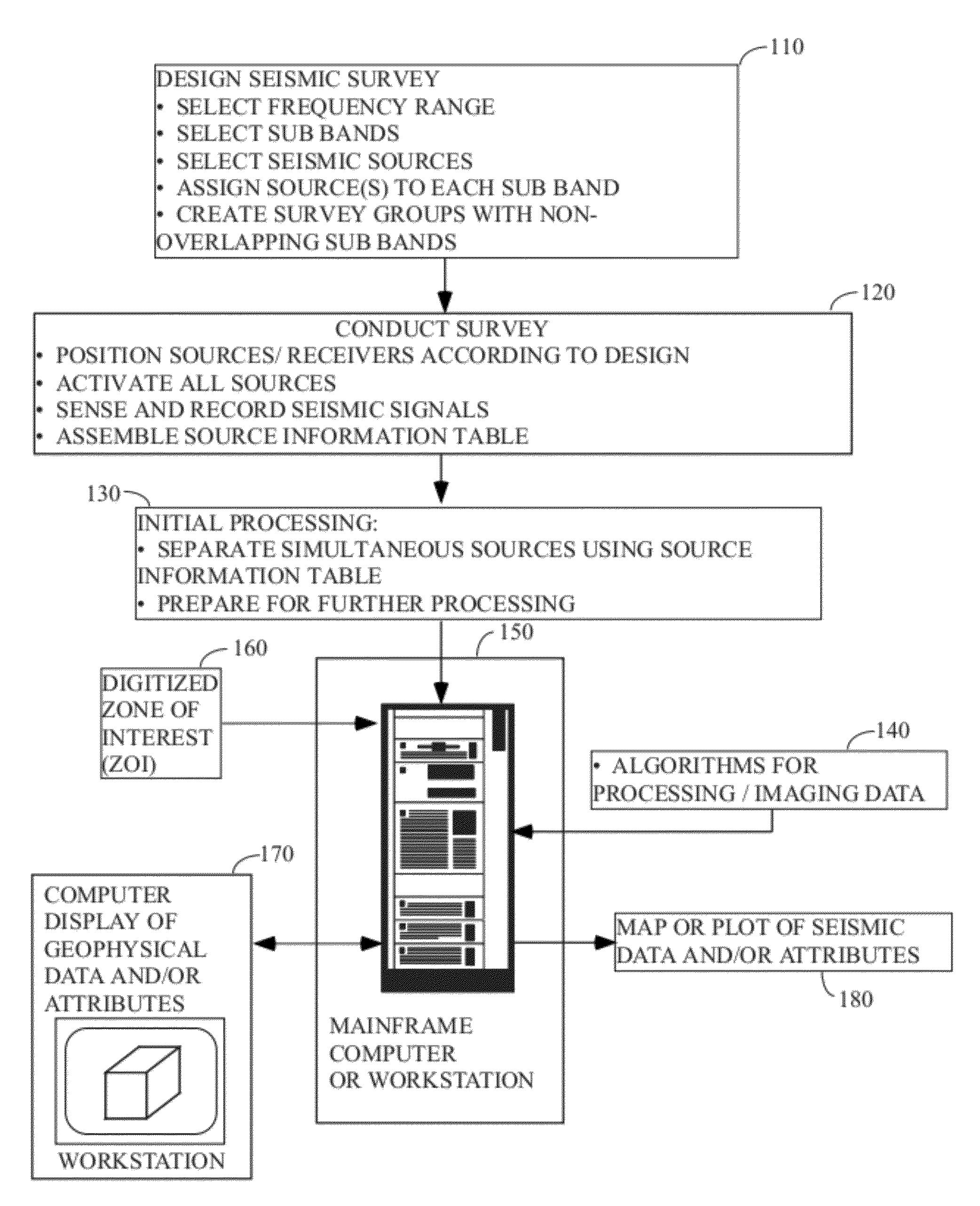
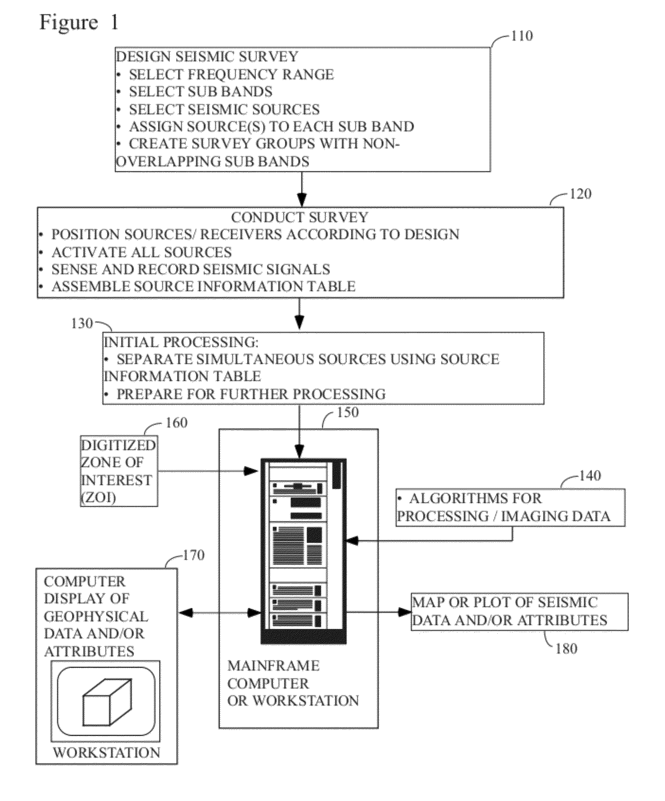
[0034]FIG. 1 illustrates the general methodology in which the instant invention would typically be used. A seismic survey is designed 110 by the explorationist to cover an area of economic interest. Field acquisition parameters (e.g., shot spacing, line spacing, fold, etc.) are typically selected in conjunction with this step, although it is common to modify the ideal design parameters slightly (or substantially) in the field to accommodate the realities of conducting the survey. The instant invention would be most useful if implemented in ...


PUM


Abstract

There is provided a method of seismic acquisition that utilizes a bank of restricted-bandwidth swept-frequency sub-band sources as a seismic source. Each seismic source will cover a restricted sub-band of frequencies, with all the sources taken together covering the full frequency range. Adjacent frequency bands may partially overlap, but non-adjacent frequency bands should not. The sources may be divided into two or more groups, with no sources covering adjacent frequency bands being placed in the same group. The sources within a group can then be separated by bandpass filtering or by conventional simultaneous source-separation techniques. The source groups may be operated simultaneously but separated in space, and the individual sources themselves may each operate independently, on a sweep schedule customized for that particular source.

Description

RELATED CASE[0001]This application claims the benefit of U.S. Provisional Patent Application Ser. No. 61 / 421,707, filed on Dec. 10, 2010, and incorporates said provisional application by reference into this disclosure as if fully set out at this point.TECHNICAL FIELD[0002]This invention relates to the general subject of seismic exploration and, in particular, to methods for acquiring seismic and other signals that are representative of the subsurface for purposes of seismic exploration.BACKGROUND OF THE INVENTION[0003]A seismic survey represents an attempt to image or map the subsurface of the earth by sending sound energy down into the ground and recording the “echoes” that return from the rock layers below. The source of the down-going sound energy might come, for example, from explosions or seismic vibrators on land, or air guns in marine environments. During a seismic survey, the energy source is placed at various locations near the surface of the earth above a geologic structur...

Claims


Application Information

Patent Timeline
IPC IPC(8): G01V1/38G01V1/24
CPCG01V1/005
Inventor DELLINGER, JOSEPH A.ABMA, RAYMOND LEE
Owner BP CORP NORTH AMERICA INC
Learn More