
Method of monitoring breaking eggs by an egg breaking apparatus in a cyclic process

a technology of breaking apparatus and breaking process, which is applied in the field of monitoring the breaking of eggs in a cyclic process by an egg breaking apparatus, can solve the problems of increasing the work difficulty of operators, and achieve the effects of less sensitive to disturbance, easy to tell, and reduced risk of disturban

Inactive Publication Date: 2012-06-14
SANOVO ENG AS
View PDF2 Cites 8 Cited by
  • Summary
  • Abstract
  • Description
  • Claims
  • Application Information

AI Technical Summary

Benefits of technology

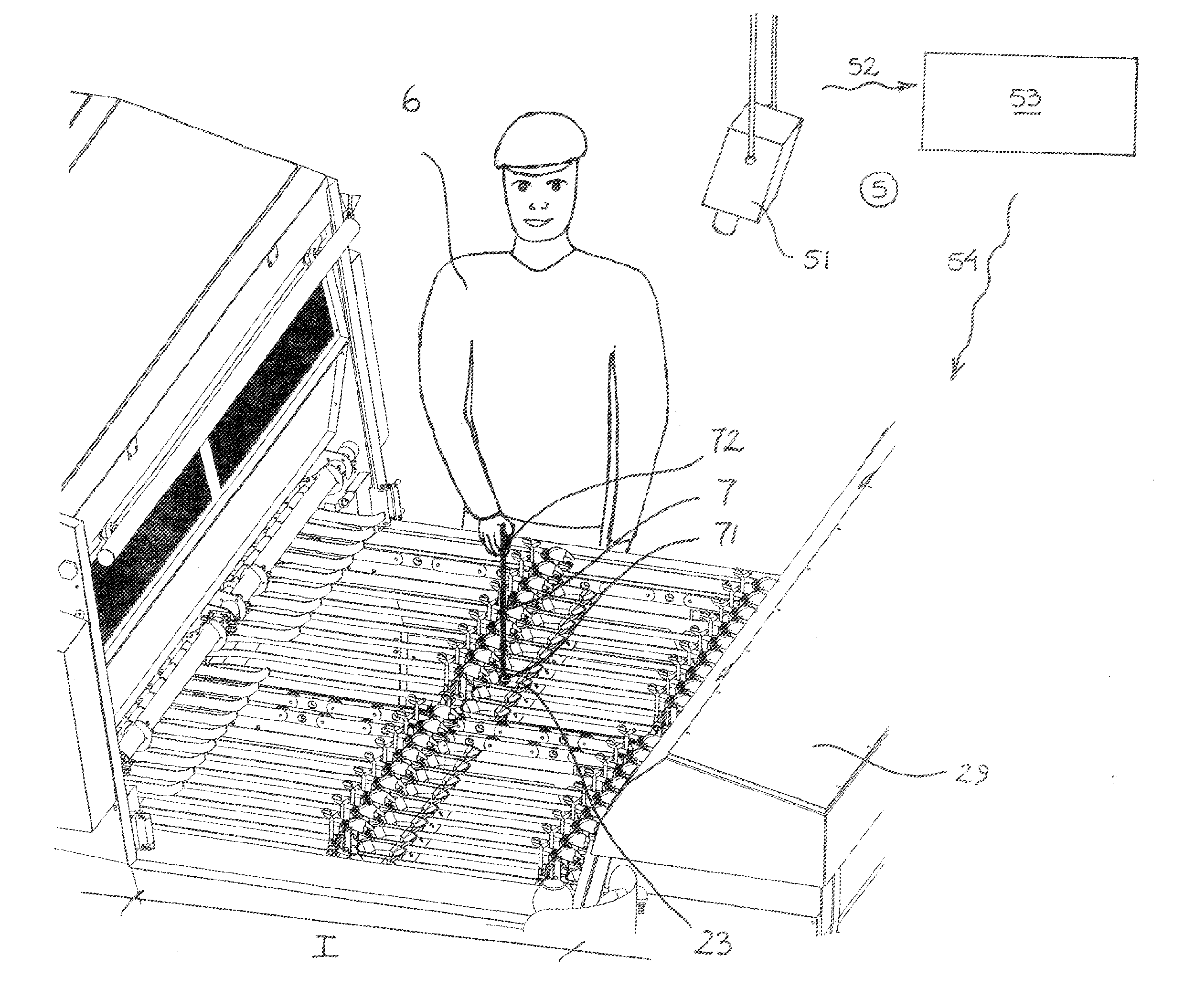
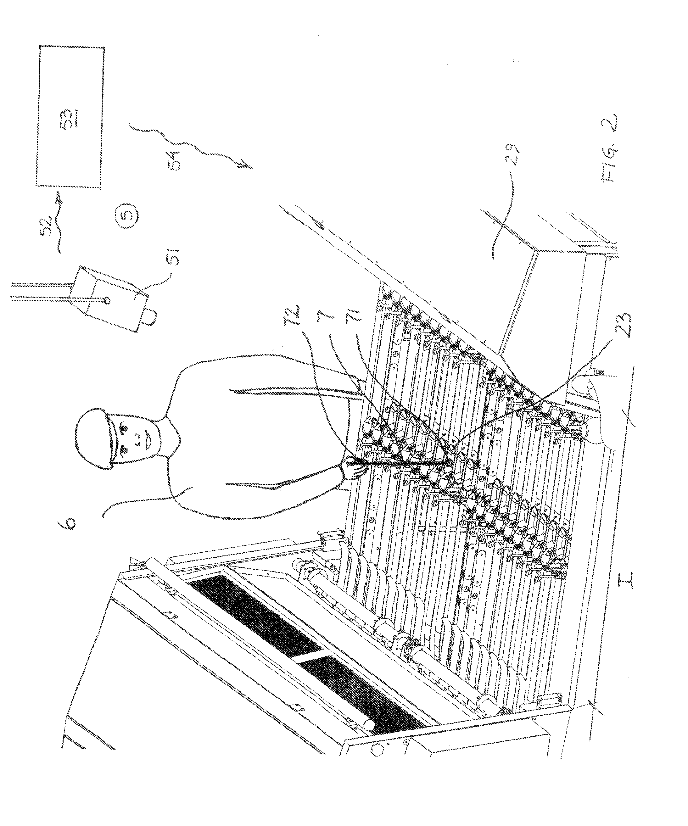
[0010]In this way the operator is capable of identifying egg receiving devices located at a distance without having to lean over the machine to activate a mechanism on the egg receiving device in question and may even reach further than his arms length, thus allowing the use of bigger machines.
[0013]An example of a remote sensor is a vision-based system, such as a digital camera connected to a computer either directly or wirelessly. The identification may then in principle be any that can be detected by the vision-based system, such as holding a coloured object or a light source at or above the egg receiving device in question. A light source has the advantage that it can be switched on and off making it easy to tell when an identification is actually made and when the pointing device is simply being moved from one position to another. The same effect may be achieved by switching the detection device, in this case the camera, on and off.
[0015]Another option is to use a pointing device including a sound source and an audio-based detection device. This may be advantageous in environments where a vision-based system is likely to be disturbed by e.g. reflections from process equipment.
[0016]When using light or sound the wave length / frequency should be chosen so that the risk of disturbance is minimized and the working environment of the operator should also be considered. Infrared light and ultrasound will be applicable in most cases, but using light or sound, which is visible / audible to humans, has the advantage that the operator will get a positive indication that the identification has been correctly made. It is of course possible to combine light and sound so that one serves the actual identification, while the other is used as an indication to the operator. A combination may also be used to provide a double detection system, which is less sensitive to disturbances and will work even in the event of malfunction on one system. The combination of difference types of light or sound is of course also possible and may possess the same advantages as described above.
[0020]Another option is to provide a detection device on each of the egg receiving devices in the form of a receiver, which the operator hits with a ray or light or sound emitted from the pointing device. This option allows the operator to be positioned further away but, again, considering the number of egg receiving devices, such methods makes great demands on the precision of the operator.
[0022]Depending on the method used, the detection device and / or pointing device may be switch on and off so that the system is only active when needed. As an example, a digital camera in a vision-based system may be in a passive mode during normal operation and activated by the operator to take a picture once he has identified an egg receiving device containing abnormal contents. Another example would be to use a pointing device, such as the angle meter described above, which is switch on for a short period when an identification is made and then switched off again.

Problems solved by technology

These methods have proven very reliable and efficient in practice, but as the machines used for breaking the eggs become bigger and bigger and run at still higher speeds, the work of the operators becomes increasingly difficult.

Method used


Image

  • Method of monitoring breaking eggs by an egg breaking apparatus in a cyclic process
  • Method of monitoring breaking eggs by an egg breaking apparatus in a cyclic process
  • Method of monitoring breaking eggs by an egg breaking apparatus in a cyclic process

Examples


Embodiment Construction

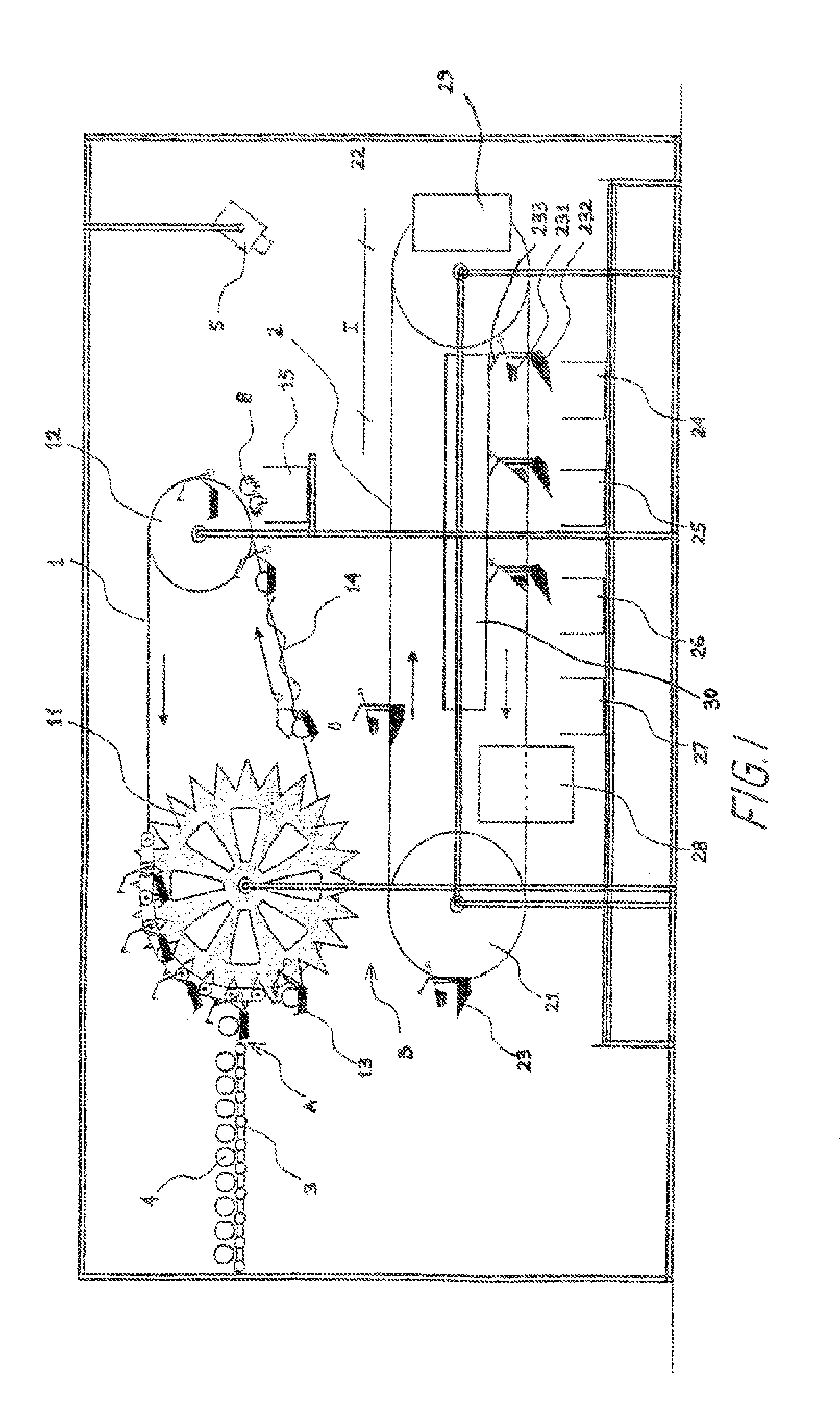
[0031]A sketch of a typical egg breaking apparatus as known from WO2007 / 095943, U.S. Pat. No. 5,858,434, U.S. Pat. No. 5,613,429 and WO89 / 05097 is shown in FIG. 1. The apparatus comprises two separate chains 1, 2 mounted on toothed turning wheels 11,12,21,22, where the uppermost chain 1 carries a plurality of egg breaking devices 13 and the lowermost chain 2 carries a plurality of egg receiving devices 23. Even though only a few egg breaking and receiving devices are shown on the respective chains, it is to be understood that in practise the number of devices on each chain are larger such that they are evenly spaced with substantially the same mutual distance on both chains. Similarly, even though FIG. 1 shows only a single row of egg breaking and receiving devices it is to be understood that each of these devices may represent a column of devices extending perpendicularly to the plane of the drawing. Such columns may be mounted on horizontal bars stretching between two parallel cha...


PUM


Abstract

The invention relates to a method of monitoring breaking of eggs by an egg breaking apparatus in a cyclic process, where eggs are broken using a plurality of egg breaking devices, each egg breaking device breaking one egg having shell and contents at a time and where the contents of each egg is collected in an egg receiving device, each egg receiving device receiving the contents of only one egg in each process cycle. An operator monitors the contents received in the egg receiving devices and identifies egg receiving devices containing abnormal contents using a pointing device. This identification is detected by a detection device and communicated to a reject mechanism, which causes the contents of the identified egg receiving device to be discharged into a rejected product receptacle. The detection device may be a remote sensor, an integrated part of the pointing device or a device located on each of the egg receiving devices.

Description

CROSS-REFERENCE TO RELATED APPLICATIONS[0001]Not ApplicableSTATEMENT REGARDING FEDERALLY SPONSORED RESEARCH OR DEVELOPMENT[0002]Not ApplicableREFERENCE TO A MICROFICHE APPENDIX[0003]Not ApplicableBACKGROUND OF THE INVENTION[0004]The present invention relates to a method of monitoring breaking of eggs in a cyclic process by an egg breaking apparatus, where eggs are broken by a plurality of egg breaking devices, each egg breaking device breaking one egg having shell and contents at a time. The contents of each egg are collected in an egg receiving device, each egg receiving device receiving the contents of only one egg in each process cycle. Remains held by each egg breaking device after the breaking of the eggshell and the collection of the contents are discharged to a waste receptacle and the contents of each egg receiving device are discharged into one or more product receptacles. At least one operator monitors the contents received in the egg receiving devices, when in an inspecti...

Claims


Application Information

Patent Timeline
Patent Type & Authority Applications(United States)
IPC IPC(8): A23L1/32A23L15/00
CPCA47J43/145
Inventor HOLST, JAN HOLM
Owner SANOVO ENG AS
Learn More