Method and device for implementing uplink synchronization

a synchronization and uplink technology, applied in the direction of synchronization arrangement, electrical apparatus, radio transmission, etc., can solve the problems of difficult to determine an optimal, waste of resources for scenarios with similar propagation delays, and inability to achieve ul comp, etc., to achieve no impact on capacity and scheduling flexibility, and easy to establish synchronization

Active Publication Date: 2012-06-14
ALCATEL LUCENT SAS
View PDF4 Cites 30 Cited by
  • Summary
  • Abstract
  • Description
  • Claims
  • Application Information

AI Technical Summary

Benefits of technology

[0014]Based on the above solution, it's advantage lines in that it's easy to establish a synchronization between the UE and all involved base stations for the UL CoMP; backward compatibility is supported without making any modification to the UE's software, hardware or protocol; and there is no impact on capacity and scheduling flexibility since it does not need to extend CP.

Problems solved by technology

UL synchronization means that UE's transmission arrives at involved base stations within their Cyclic Prefix (CP)'s coverage; otherwise, if the UL transmission arrives at a base station before or late to its CP's coverage, the impacted base station may not decode this UL transmission correctly, hence the UL CoMP may not be achieved.
1. It is very hard to determine an optimal CP length to cover different UL CoMP scenarios. For example, for scenarios where propagation delays to the involved base stations are similar, a small CP length is enough, however, it is not applicable to scenarios where the propagation delays varied dramatically. Also the longer CP will result in resource waste for scenarios with similar propagation delays.
2. This longer CP results in large overhead and leads to UL capacity loss. The reason is that the symbols which should be used to send data are now occupied by extended CP.
3. This solution may not support legacy UEs.
4. Scheduling flexibility is restricted since the UL CoMP may only be scheduled in the frame with longer CP length.

Method used


Image

  • Method and device for implementing uplink synchronization
  • Method and device for implementing uplink synchronization
  • Method and device for implementing uplink synchronization

Examples


Embodiment Construction

[0023]Preferred embodiments of the present invention will now be explained in detail with reference to the accompanying drawings. Details and functions that are not necessary for the present invention are omitted in the description so as not to obscure the understanding of the present invention.

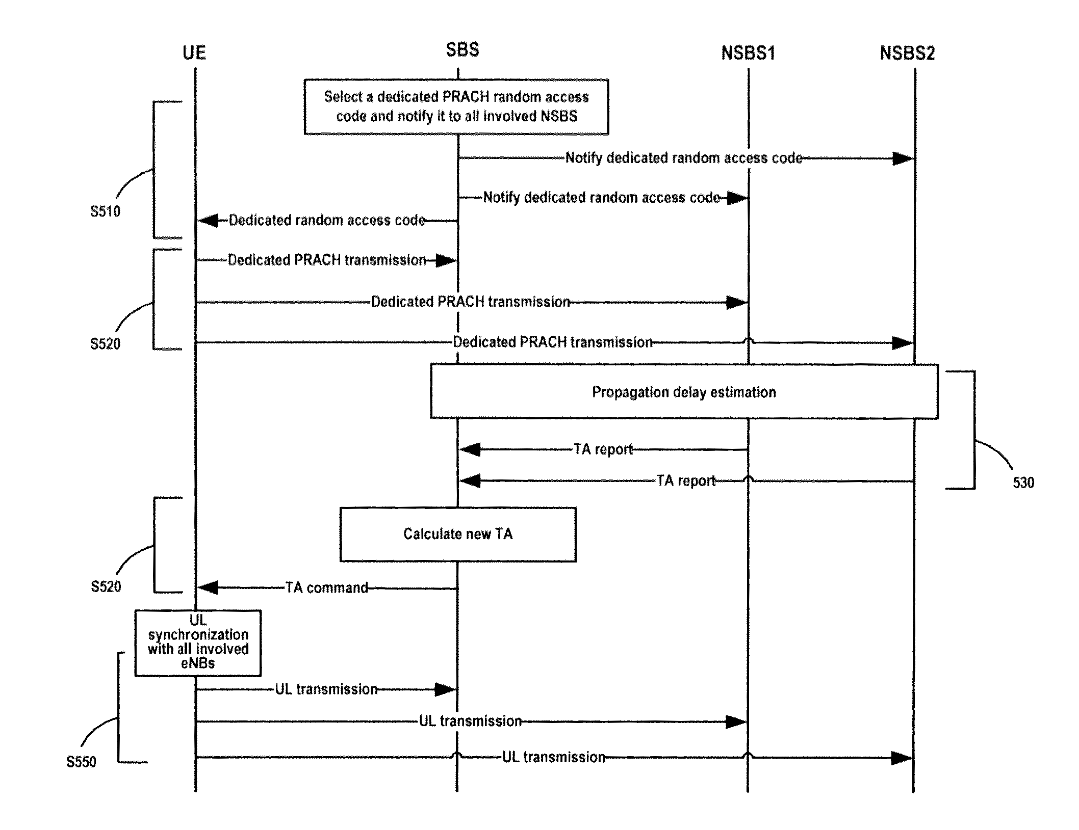
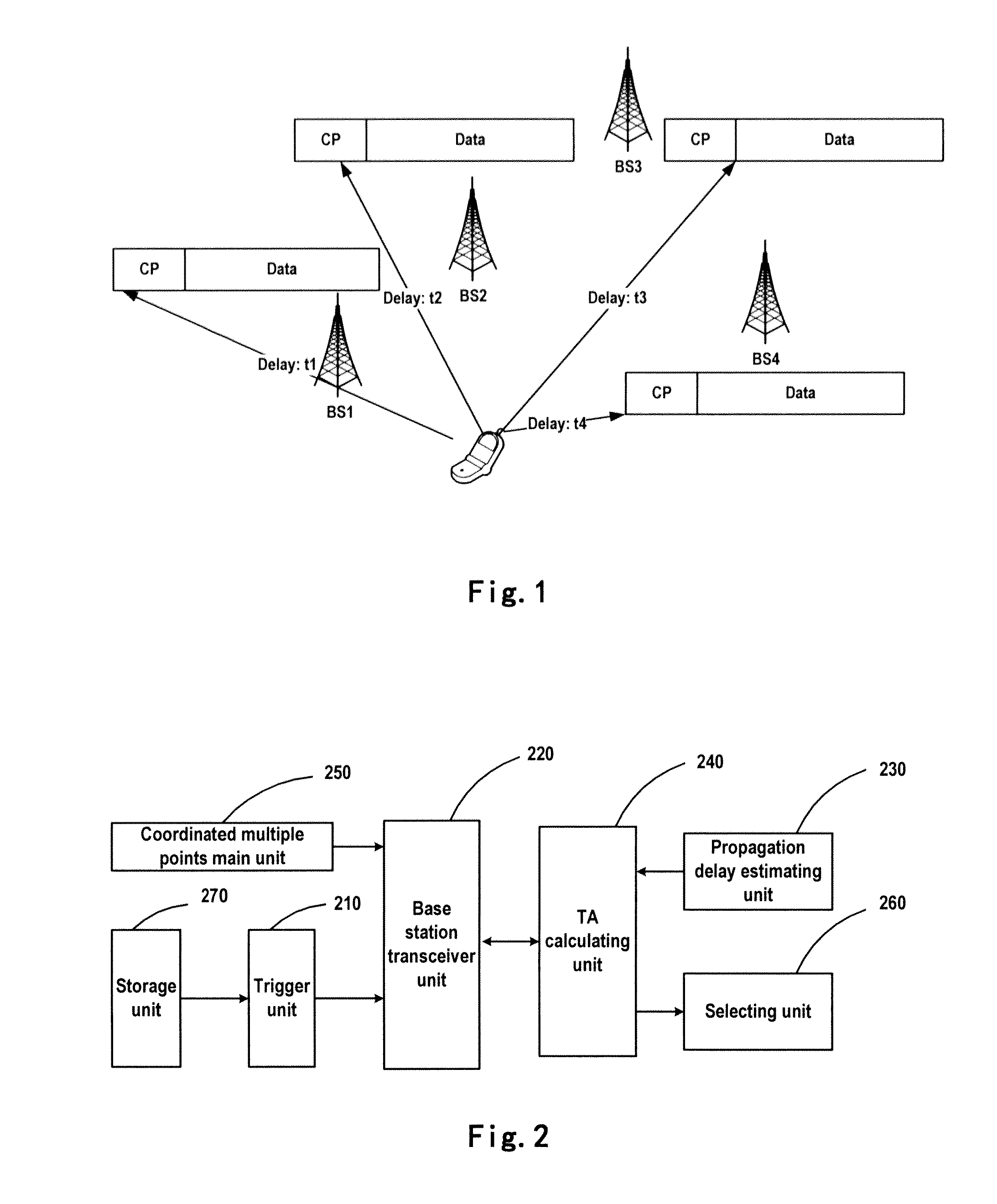
[0024]In an embodiment of the present invention, a system for uplink synchronization is proposed as shown in FIG. 1, which includes the following base stations and User Equipment (UE).

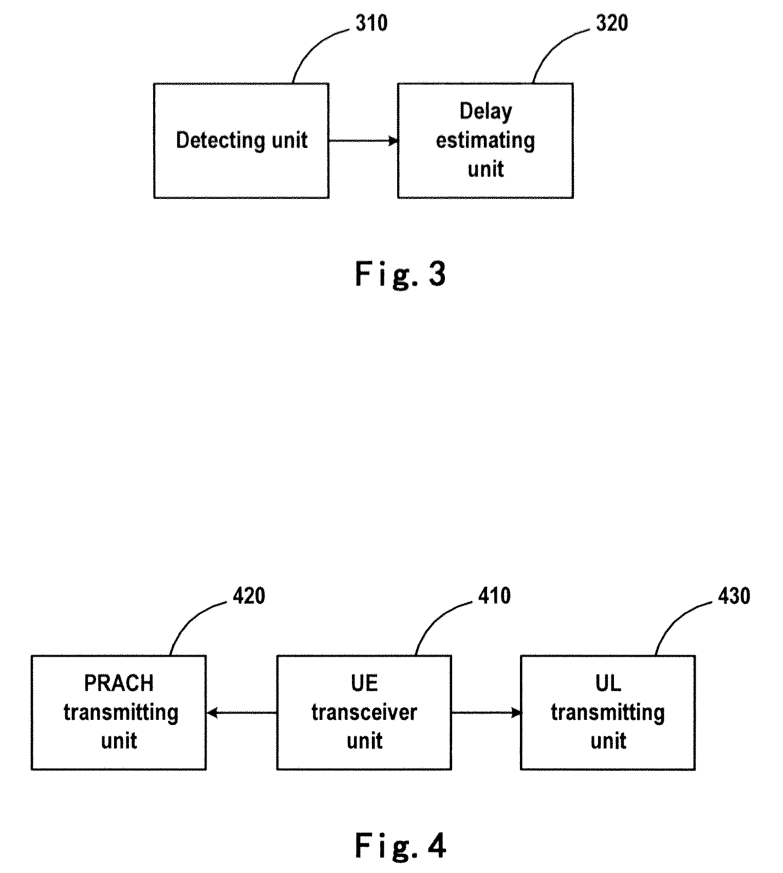
[0025]Also, a base station as shown in FIG. 2 is proposed, which includes a trigger unit 210 configured to instruct a UE to perform a dedicated Physical Random Access Channel (PRACH) transmission; a base station transceiver unit 220 configured to send the instruction from the trigger unit to the UE; a propagation delay estimating unit 230 configured to estimate the propagation delay based on detection of the dedicated PRACH transmission performed by the UE, so as to derive first timing information; a timing adva...


PUM


Abstract

Embodiments of the invention provide a method and device for establishing uplink (UL) synchronization. The method includes: instructing a UE to perform a dedicated PRACH transmission; calculating a timing advance (TA) according to first timing information derived by itself and second timing information received from a plurality of non-serving base stations, and sending the timing advance to the UE to enable the UE to establish the uplink synchronization with involved base stations according to the timing advance, wherein the first timing information and the second timing information are associated with propagation delays of the dedicated PRACH transmission performed by the UE. With the above solution, it may be easy to establish UL synchronization between the UE and all involved base stations for UL CoMP.

Description

FIELD OF THE INVENTION[0001]The present invention relates to wireless communication technology, and more particularly to a method and device for implementing uplink synchronization.BACKGROUND OF THE INVENTION[0002]Uplink (UL) Coordinated Multiple Points (CoMP) has been accepted in 36.814 as an important candidate for enhancing UL capacity in an LTE-advanced system. For UL CoMP, more than one base stations (BSs) are configured to receive the UL transmission from a UE and the received signals are combined to get combining gain. The most important baseline for implementation of UL CoMP is that all involved base stations must be able to receive the UL transmissions from a UE, that is, the UE should perform UL synchronization with all involved base stations prior to the UL transmission so as to solve the different propagation delays between UE and involved base stations. For example, as shown in FIG. 6, this issue due to the difference between the propagation delays t1 and t2 for the inv...

Claims


Application Information

Patent Timeline
Patent Type & Authority Applications(United States)
IPC IPC(8): H04W74/08H04W68/00H04W56/00
CPCH04W92/10H04W56/0045H04W56/00
Inventor YANG, TAO
Owner ALCATEL LUCENT SAS
Why Eureka
Try Eureka