
Sliding type portable terminal

a portable terminal and flip-type technology, applied in the field of flip-type portable terminals, can solve the problems of reducing the coupling state affecting the service life of the first and second housings, so as to achieve smooth sliding operation, reduce frictional area, and maintain the coupling. the effect of durable coupling

Inactive Publication Date: 2012-06-14
SAMSUNG ELECTRONICS CO LTD
View PDF4 Cites 0 Cited by
  • Summary
  • Abstract
  • Description
  • Claims
  • Application Information

AI Technical Summary

Benefits of technology

[0013]Accordingly, the present invention has been made to solve the above-mentioned problems occurring in the prior art, and an aspect of the present invention provides a sliding type portable terminal which can prevent unnecessary movement of housings by coupling the housings in a stable manner.
[0014]Also, another aspect of the present invention provides a sliding type portable terminal capable of stably maintaining the coupled state between the housings, while allowing a smooth sliding therebetween.
[0015]Still another aspect of the present invention provides a sliding type portable terminal which can alleviate the deformation of components even when external impacts or the like are applied thereto.
[0019]It should be appreciated that the sliding type portable terminal as constructed above can reduce a frictional area in a sliding operation between the housings by forming the opening at the guide rib, thus achieving a smooth sliding operation of one housing against the other. Furthermore, compared with a conventional sliding type portable terminal without an opening at a guide rib, it is possible to provide a durable coupling between the guide member and the second housing. In other words, as the friction area in the sliding operation is reduced with the aid of opening, it is possible to accomplish a closer coupling between the guide member and the second housing, while maintaining a smooth sliding operation therebetween.
[0020]Further, it is possible to prevent unnecessary movement of the second housing as the opening formed at the guide rib acts as a buffer space which allows the second housing to be deformed in a certain degree when an external force within a permissible range is applied to the second housing, thus makes it possible to prevent the guide member or the like from permanently being deformed. That is, deformations of the second housing due to an external force within a permissible range can be restored to its initial shape by coupling structures between the components constituting the second housing and the restoration force of the same. Accordingly, without using a metallic material, it is possible to construct a slide module of a high rigidity synthetic resin.

Problems solved by technology

An earlier bar-type terminal had drawbacks in that a keypad for data input is always exposed to the outside causing a malfunction due to impact.
The design also impose a limitation in miniaturization due to a problem of providing a distance between the microphone part and the speaker part.
Although the flip covers a keypad of a data input means to prevent its malfunction, the flip-type terminal also has a limitation in miniaturizing its size as it requires to provide a distance between the microphone part and the speaker part.
However, such a gap may cause the second housing to move in a different direction from its original direction, which makes it difficult to stably maintain the coupled state of the first and second housings.
However, in the case that the guide member or the like is permanently deformed due to external impacts, it has drawbacks in that the sliding is not smoothly made or even impossible.

Method used


Image

  • Sliding type portable terminal
  • Sliding type portable terminal
  • Sliding type portable terminal

Examples


Embodiment Construction

[0028]Hereinafter, embodiments of the present invention will be described with reference to the accompanying drawings. For the purposes of clarity and simplicity, a detailed description of known functions and configurations incorporated herein will be omitted as it may make the subject matter of the present invention rather unclear.

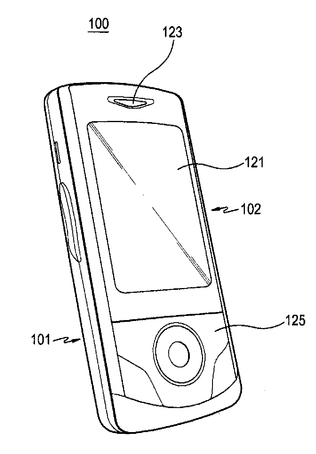
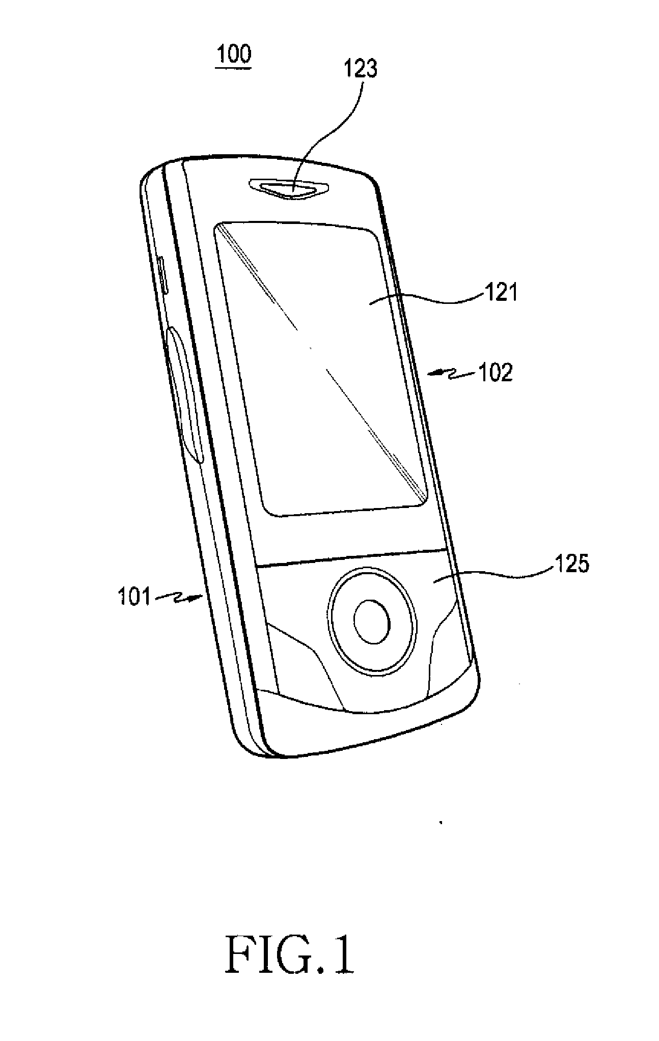
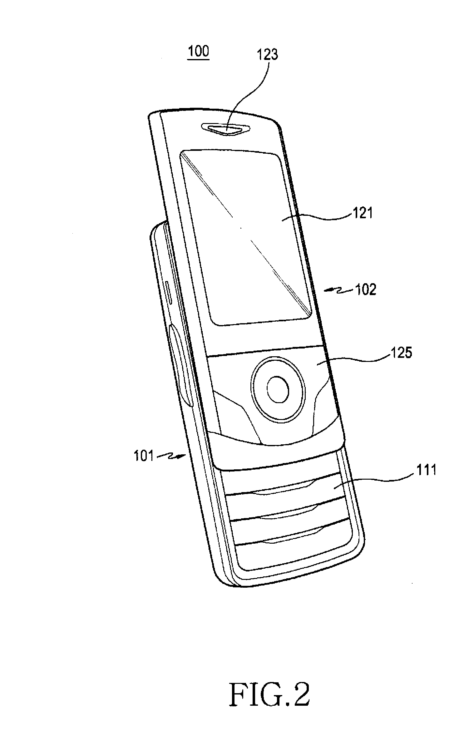
[0029]Referring to FIGS. 1 and 2, a sliding type portable terminal 100 in accordance with an exemplary embodiment of the present invention includes a first housing 101, and a second housing 102, which is slidably coupled with the first housing 101 while facing the first housing 101.

[0030]The first housing 101 is provided with a keypad 111 installed on one surface thereof, and the keypad 111 is selectively opened and closed through a sliding of the second housing 102. A guide member 201 (see FIG. 3) is slidably mounted over the keypad 111 area in the first housing 101. The guide member 201 is designed to couple the second housing 102 to the first housing 1...


PUM


Abstract

A sliding type portable terminal includes: a first housing; a second housing coupled with the first housing in a state in which the second housing is slidable in one direction while facing the first housing; a guide member mounted on one surface of the first housing; and guide ribs provided at the guide member and slidably coupled with one surface of the second housing, wherein an opening is formed through each of the guide ribs, and the guide member extends along a direction in which the second housing slides. The sliding type portable terminal can achieve a smooth sliding operation of one housing against the other and provide a durable coupling between the guide member and the second housing by reducing a frictional area in a sliding operation between the housings through formation of the opening at the guide rib.

Description

CLAIM OF PRIORITY[0001]This application claims the priority under 35 U.S.C. §119 of an application entitled “Sliding Type Portable Terminal” filed in the Korean Intellectual Property Office on Dec. 9, 2010 and assigned Serial No. 10-2010-0125237, the contents of which are hereby incorporated by reference.BACKGROUND OF THE INVENTION[0002]1. Field of the Invention[0003]The present invention relates to a portable terminal, and more particularly to a sliding type portable terminal including a pair of housings facing each other so that one housing can slide with respect to the other housing.[0004]2. Description of the Related Art[0005]In general, a portable terminal is classified into a bar-type, a flip-type, a folder-type, and a sliding type terminal.[0006]A bar-type terminal corresponds to a type in which a data input / output means, a microphone part and a speaker part are mounted within single body housing. An earlier bar-type terminal had drawbacks in that a keypad for data input is a...

Claims


Application Information

Patent Timeline
Patent Type & Authority Applications(United States)
IPC IPC(8): H04W88/02
CPCH04M1/0237
Inventor SON, KI-BOKHUR, CHANG-WON
Owner SAMSUNG ELECTRONICS CO LTD
Learn More