
Soft plate soft panel bonded multi layer armor materials

a technology of soft panels and armor materials, applied in the direction of transportation and packaging, manufacturing tools, other domestic articles, etc., to achieve the effect of reducing the effective stiffness of the plate and allowing flexur

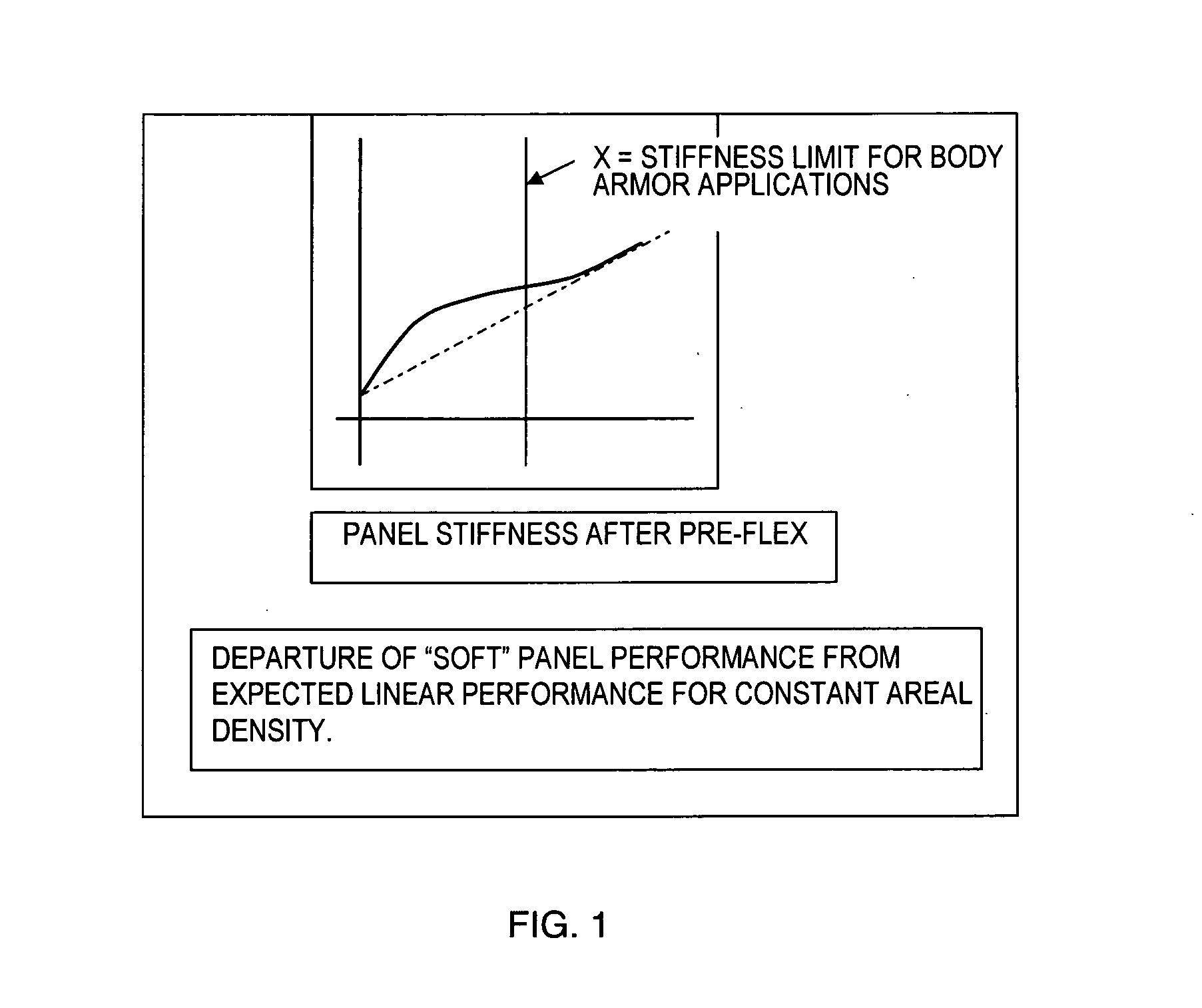
Active Publication Date: 2012-06-21
WARWICK MILLS INC
View PDF14 Cites 32 Cited by
  • Summary
  • Abstract
  • Description
  • Claims
  • Application Information

AI Technical Summary

Benefits of technology

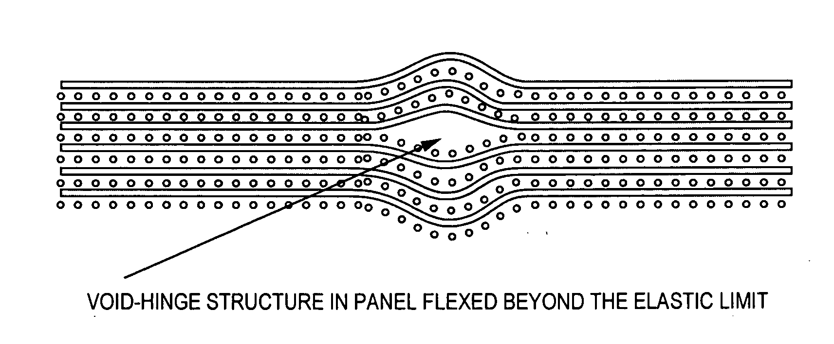
[0009]Surface buckling and the accompanying interior voids occurring in the panel under bending stress tends to form as hinge line segments oriented in a threadline direction of the threads or strands of an interior sheet, layer or ply. These hinge points reduce the effective stiffness of the plate as a whole but do not affect the ballistic or singular point of impact performance in a linear way as long as the width of the hinge lines is proportionally small as compared to the diameter of the ballistic object or bullet of interest. However, as a result of this relationship, the hinge-like buckle void limits the maximum practical thickness of the basic system. As the thickness of the plate or laminate structure goes up, the hinge-buckle zone width increases in proportion to the thickness, in order to permit flexure. As the in-plane cross section dimension of the hinge-buckle zone approaches the bullet diameter, the performance of the panel approaches the performance of the separate laminate layers rather than the solid plate. For this reason, there may be further utility in a layered arrangement of such panels.

Problems solved by technology

However, it has been discovered that by building or creating flex points in a molded panel, ballistic performance can be unexpectedly and significantly increased without significant sacrifices to flexibility, or to put it conversely, flexibility can be unexpectedly and significantly increased without significant sacrifice to ballistic performance.

Method used


Image

  • Soft plate soft panel bonded multi layer armor materials
  • Soft plate soft panel bonded multi layer armor materials
  • Soft plate soft panel bonded multi layer armor materials

Examples


Embodiment Construction

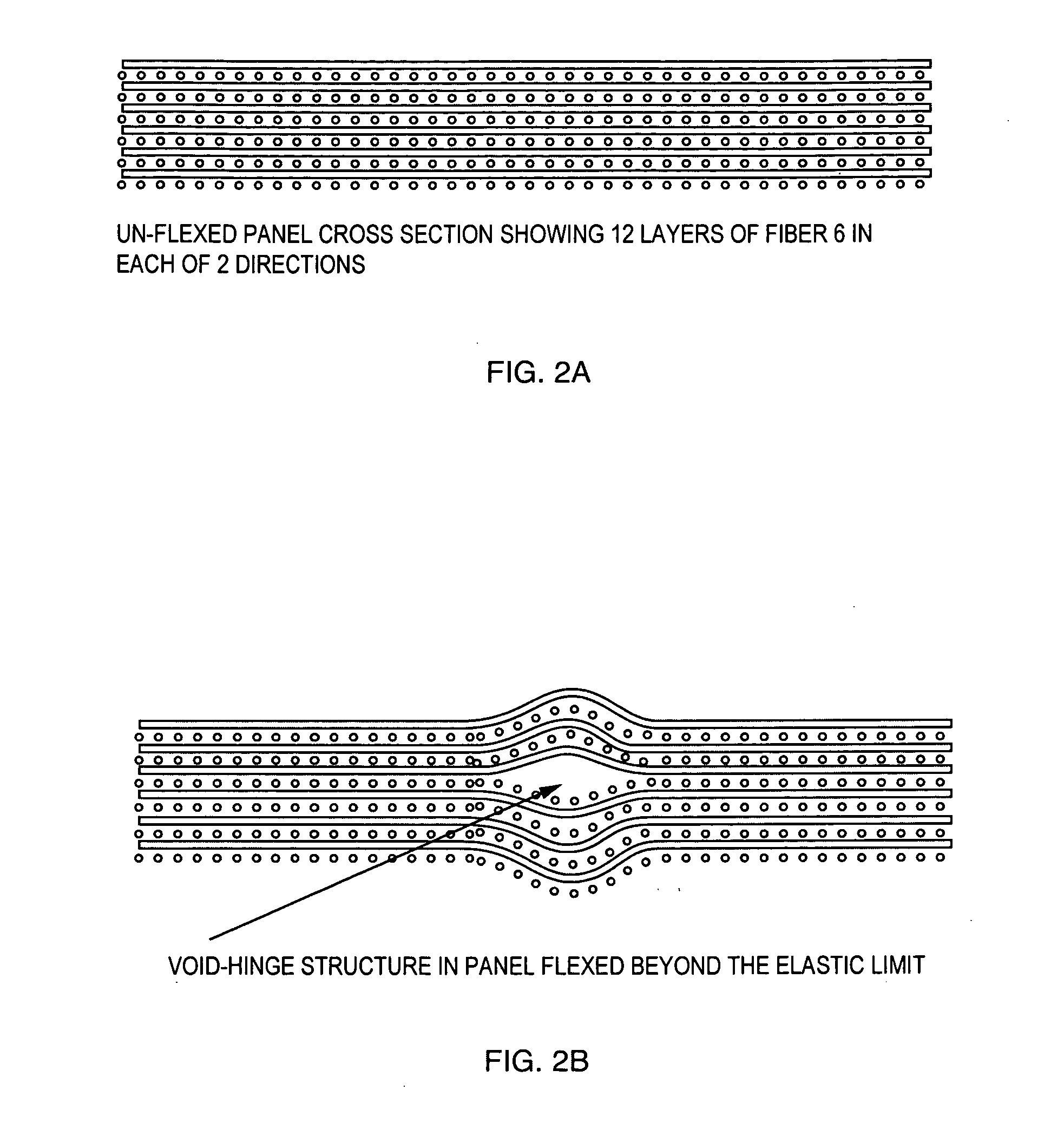
[0017]The invention is susceptible of many embodiments, including methods and structures. Referring to FIG. 2A, there is illustrated a diagrammatic cross section view of a first embodiment bonded panel or plate section showing 12 bonded layers of fiber, with six layers oriented with thread lines running in one direction, and interspersed with the other six layers which are oriented with their threadlines running in another direction, the directions being nominally at right angles to each other. Other configurations may have woven or unwoven sheets of fibers with threadlines of respective layers oriented at other than right angles, such as at uniform 60 or 45 degrees or more or less apart, or with non-uniform angular orientations. While the discussion may often refer to UHMWPE fibers, it will be appreciated that the term is used for its ready association with fibers of this general characteristic and high tenacity and that the technology claimed is applicable to any fiber type of sim...


PUM

PropertyMeasurementUnit
Pressureaaaaaaaaaa
Pressureaaaaaaaaaa
Diameteraaaaaaaaaa

Abstract

A flexible armor system includes a rigid panel of a stiffness calculated to resist penetration by a known ballistic object, made from multiple layers of Ultra High Molecular Weight Poly-Ethylene fibers or other high tenacity fibers, which is then pre-flexed beyond its elastic bending limit to create a distributed pattern of surface buckling, with localized areas of interior delamination, which together function as bending or hinge lines to provide flexibility to the otherwise rigid panel and thereby lower its overall stiffness to less than that calculated for the rigid panel to resist the ballistic object. The areas of delamination have a width of less than one half the diameter of the ballistic object.

Description

RELATED APPLICATIONS[0001]This application claims priority to pending U.S. Provisional Application Ser. No. 60 / 983,731, filed Oct. 30, 2007BACKGROUND OF THE INVENTION[0002]Ultra High Molecular Weight Poly-Ethylene (UHMWPE) is commonly used in armor applications. Its high strength combined with its elongation properties makes it an ideal material for stopping ballistic threats. Currently there are two common forms of the material which are used in armor applications. “Soft” applications where plies of UHMWPE are layered in conjunction with one another to preserve flexibility, and “hard” applications where the layers of UHMWPE are heated and pressed together to bond the material into a solid.[0003]“Soft” applications are most common in the body armor industry, where flexibility is required in order to preserve comfort. The downside is that the same amount of UHMWPE when bonded together will yield much higher performance (i.e. will stop ballistic threats with much more energy).[0004]Th...

Claims


Application Information

Patent Timeline
IPC IPC(8): F41H5/04B23P17/04B29C53/04
CPCB32B5/12B32B5/26B32B2571/02F41H5/0485B32B5/022B32B5/04Y10T29/49826B32B3/28B32B2250/05B32B2250/20B32B2262/0253B32B2307/558B32B7/045B32B7/05
Inventor HOWLAND, CHARLES A.WOODWARD, ANDREW
Owner WARWICK MILLS INC
Learn More