Valve timing control apparatus

Active Publication Date: 2012-06-21
AISIN SEIKI KK
View PDF6 Cites 15 Cited by
  • Summary
  • Abstract
  • Description
  • Claims
  • Application Information

AI Technical Summary

Benefits of technology

[0027]According to the fourth characterizing feature of the valve timing control apparatus relating to the present invention, the first lock mechanism and the second lock mechanism respectively include a lock groove formed in either one of the driving-side rotary body and the driven-side rotary body, and the first lock mechanism and the second lock mechanism share a common lock member provided in the other one of the driving-side rotary body and the driven-side rotary body having the respective lock groove to be projectable/retractable into/from the lock groove, the lock member being projectable into the respective lock groove to be retained in this lock groove, thereby to restrain relative rotational movement of the driven-side rotary body relative to the driving-side rotary body to either the first predetermined phase or the second predetermined phase.
[0028]With the above-described arrangement, the first lock mechanism and the second lock mechanism respectively have a lock groove and share one same lock mem

Problems solved by technology

However, even when the internal combustion engine is stopped at this decompression phase, it is sometimes difficult to maintain the r

Method used


Image

  • Valve timing control apparatus
  • Valve timing control apparatus
  • Valve timing control apparatus

Examples


first alternative embodiment

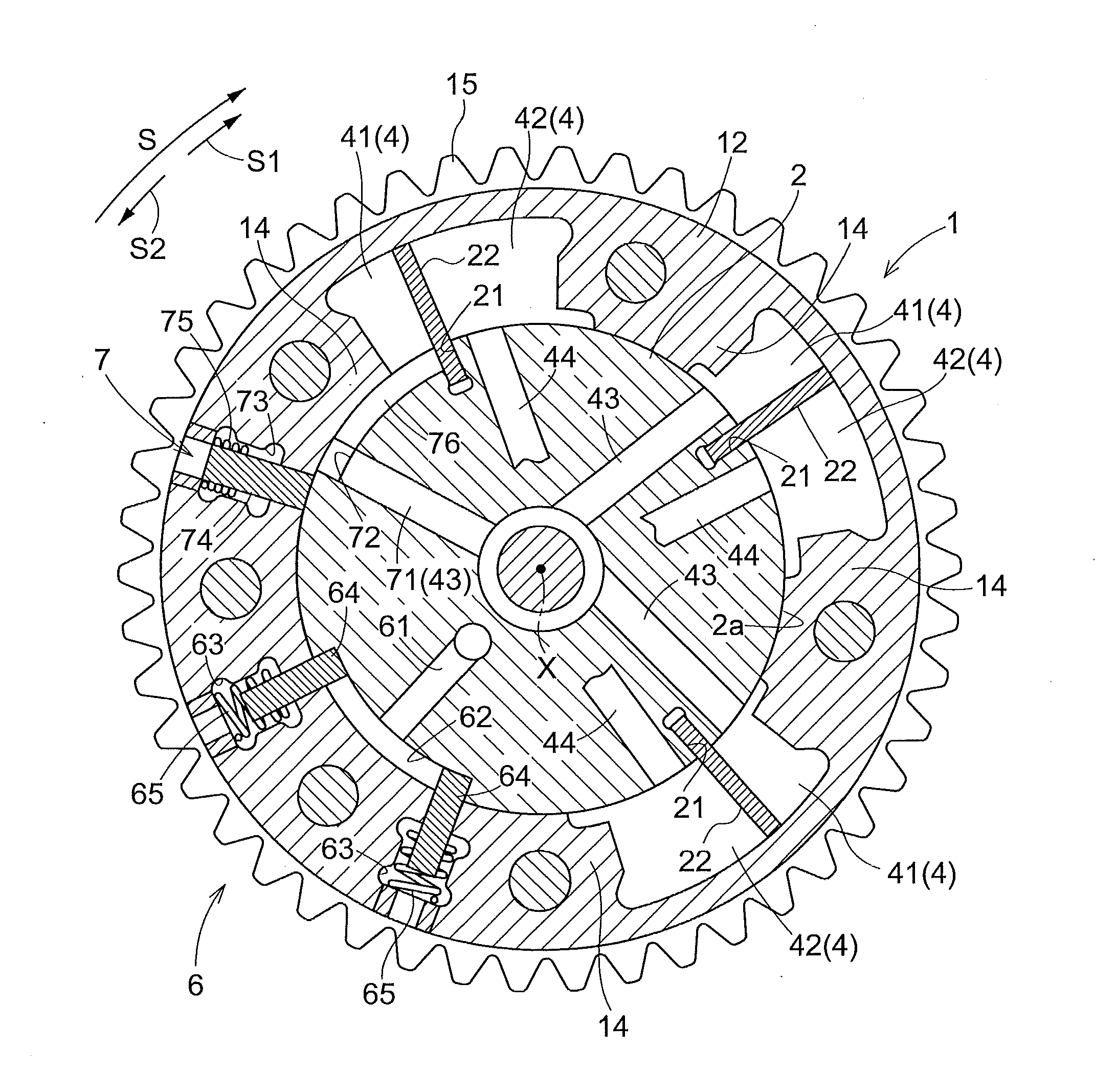
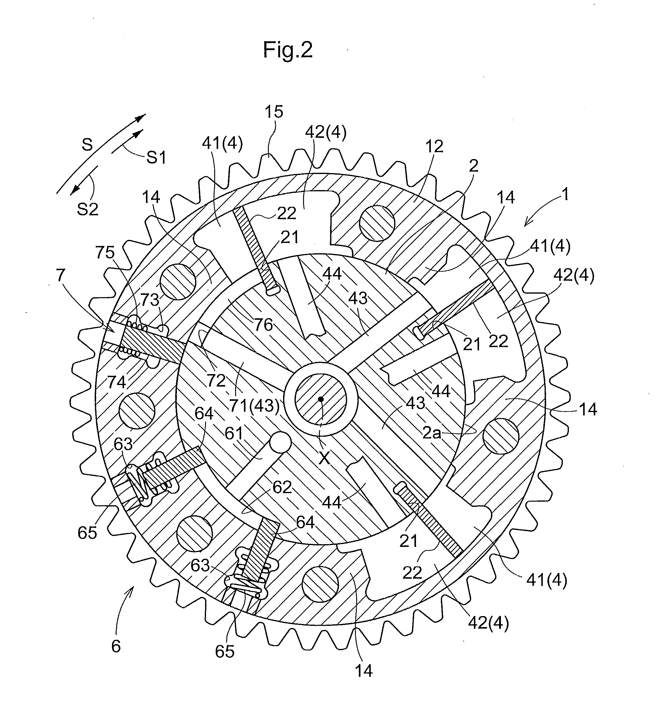
[0098]In the foregoing embodiment, there was explained the exemplary arrangement wherein the intermediate lock mechanism 6 and most retarded angle lock mechanism 7 respectively include the lock groove 62 and the lock member 64, or the lock groove 72 and the lock member 74. Alternatively, the lock member can be shared by the intermediate lock mechanism 6 and the most retarded angle lock mechanism 7. That is, according to such arrangement, the intermediate lock mechanism 6 and the most retarded angle lock mechanism 7 respectively include a lock groove formed in the inner rotor 2 and share a common lock member which is provided in the outer rotor 12 to be projectable / retractable into / from the respective lock groove, so that when protruded into the lock groove, the lock member is retained in this lock groove to restrain the relative rotational phase of the inner rotor 2 relative to the housing 1 to the intermediate locked phase or the most retarded angle phase. This alternative embodime...

second alternative embodiment

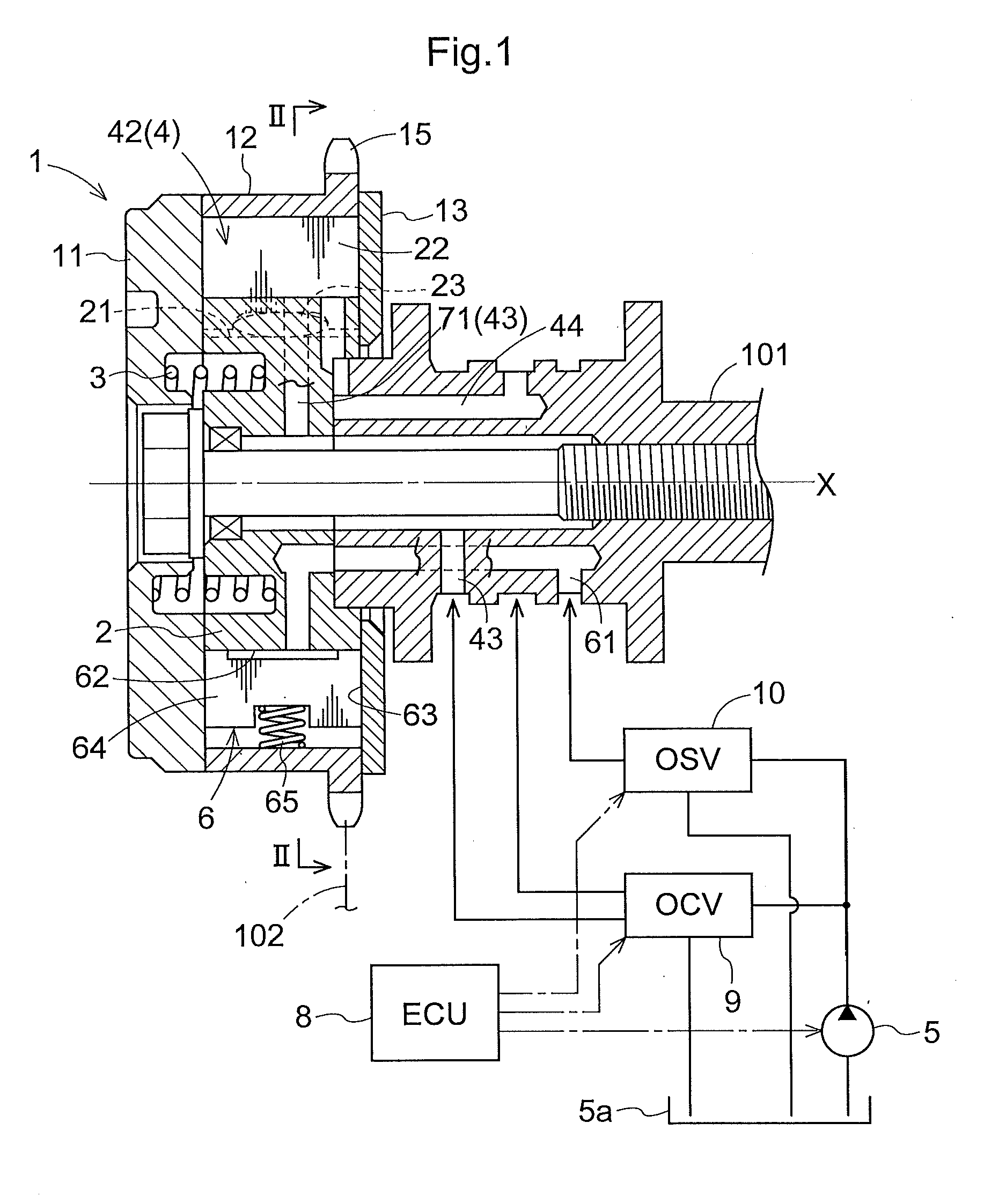
[0104]In the foregoing embodiment, the intermediate lock mechanism 6 is controlled by the OSV 10 and the most retarded angle lock mechanism 7 is controlled by the OCV 9. The invention is not limited thereto. Alternatively, both the intermediate lock mechanism 6 and the most retarded angle lock mechanism 7 can be controlled by the OSV 10 alone. This alternative embodiment will be described next with reference to FIGS. 11 through 13. Explanation of identical arrangement to the foregoing embodiment will be omitted. Further, identical members or components will be denoted with same reference marks / numerals. As shown in FIG. 11, the layouts of the housing 1, the inner rotor 2, the oil pump 5, the OCV 9, the OSV 10, etc. are identical to those in the foregoing embodiment.

[0105]As shown in FIG. 12, the intermediate lock passage 61 is branched on the side of the inner rotor 2, with one of them being connected to the intermediate lock groove 62, the other thereof being connected to the most ...


PUM


Abstract

A valve timing control apparatus includes a driving-side rotary body, a driven-side rotary body, a fluid pressure chamber partitioned into a retard angle chamber and an advance angle chamber by a partitioning portion provided in at least one of the driving-side rotary body and the driven-side rotary body, a fluid control mechanism for controlling feeding of working fluid from a working fluid pump for feeding the working fluid to the fluid pressure chamber and controlling also discharging of the working fluid from the fluid pressure chamber, a first lock mechanism capable of restraining a relative rotational phase to a first predetermined phase between a most retarded angle phase and a most advanced angle phase, and a second lock mechanism capable of restraining the relative rotational phase to a second predetermined phase different from the first predetermined phase.

Description

TECHNICAL FIELD [0001]The present invention relates to a valve timing control apparatus for controlling opening / closing timings of an intake valve and an exhaust valve of an internal combustion engine for use in an automobile,BACKGROUND ART [0002]Conventionally, as shown in PTL 1, there is known a valve timing control apparatus including a driving-side rotary body (“a rotation transmitting member” in the document), a driven-side rotary body (“a rotary member” in the document), a fluid pressure chamber formed by the driving-side rotary body and the driven-side rotary body and partitioned into a retard angle chamber and an advance angle chamber by a partitioning portion (“a vane” in the document) provided in the driven-side rotary body, and a fluid control mechanism (“a control valve” in the document) for controlling feeding of the working fluid from a working fluid pump (“an oil pump” in the document) for feeding working fluid and controlling also discharging of the working fluid fro...

Claims


Application Information

Patent Timeline
IPC IPC(8): F01L1/34
CPCF01L1/3442F01L2001/34463F01L2001/34483F01L2001/34473F01L2001/34476F01L2001/34466
Inventor KOBAYASHI, MASAKIADACHI, KAZUNARIUOZAKI, MITSURUFUJIWAKI, KENJIMASUDA, SHOHEI
Owner AISIN SEIKI KK
Why Eureka
Try Eureka