Supercharge Your Innovation With Domain-Expert AI Agents!

Remote weapon system

a weapon system and remote technology, applied in the field of remote weapon systems, can solve the problems of inaccurateness and significant waste of ammunition

Active Publication Date: 2012-06-21
KONGSBERG DEFENCE & AEROSPACE
View PDF8 Cites 8 Cited by
  • Summary
  • Abstract
  • Description
  • Claims
  • Application Information

AI Technical Summary

Benefits of technology

[0009]The input parameters may further include ammunition type and / or at least one climatic parameter. The ammunition type is preferably associated with a predetermined footprint and time of flight for that particular type of ammunition. The at least one climatic parameter may include wind and / or temperature. Accounting for these input parameters may improve the accuracy of the above calculation.
[0012]In one particular embodiment of the present invention, the fire control unit is configured to determine the geographical area based on a theoretical calculation of movement of the target starting from said position. The fire control unit may for instance be configured to increase the geographical area over time. Also, the input parameters may further include target speed, to more accurately and efficiently determine the geographical area. The target speed may for instance be divided into three levels: low (for walking / crawling target), medium (for running target), and high (for vehicle target). The target speed may be entered manually by an operator.

Problems solved by technology

This may however be inaccurate, and the waste of ammunition may be significant.

Method used


Image

  • Remote weapon system
  • Remote weapon system
  • Remote weapon system

Examples


Embodiment Construction

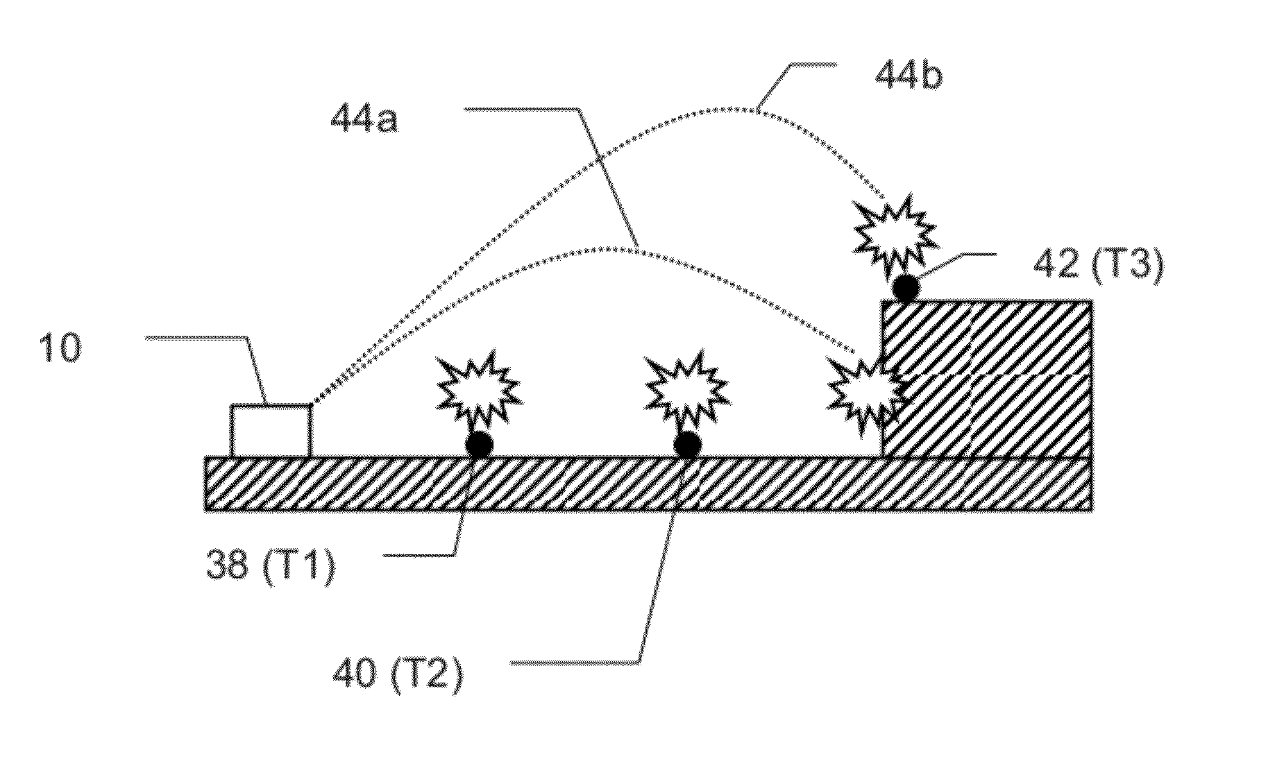
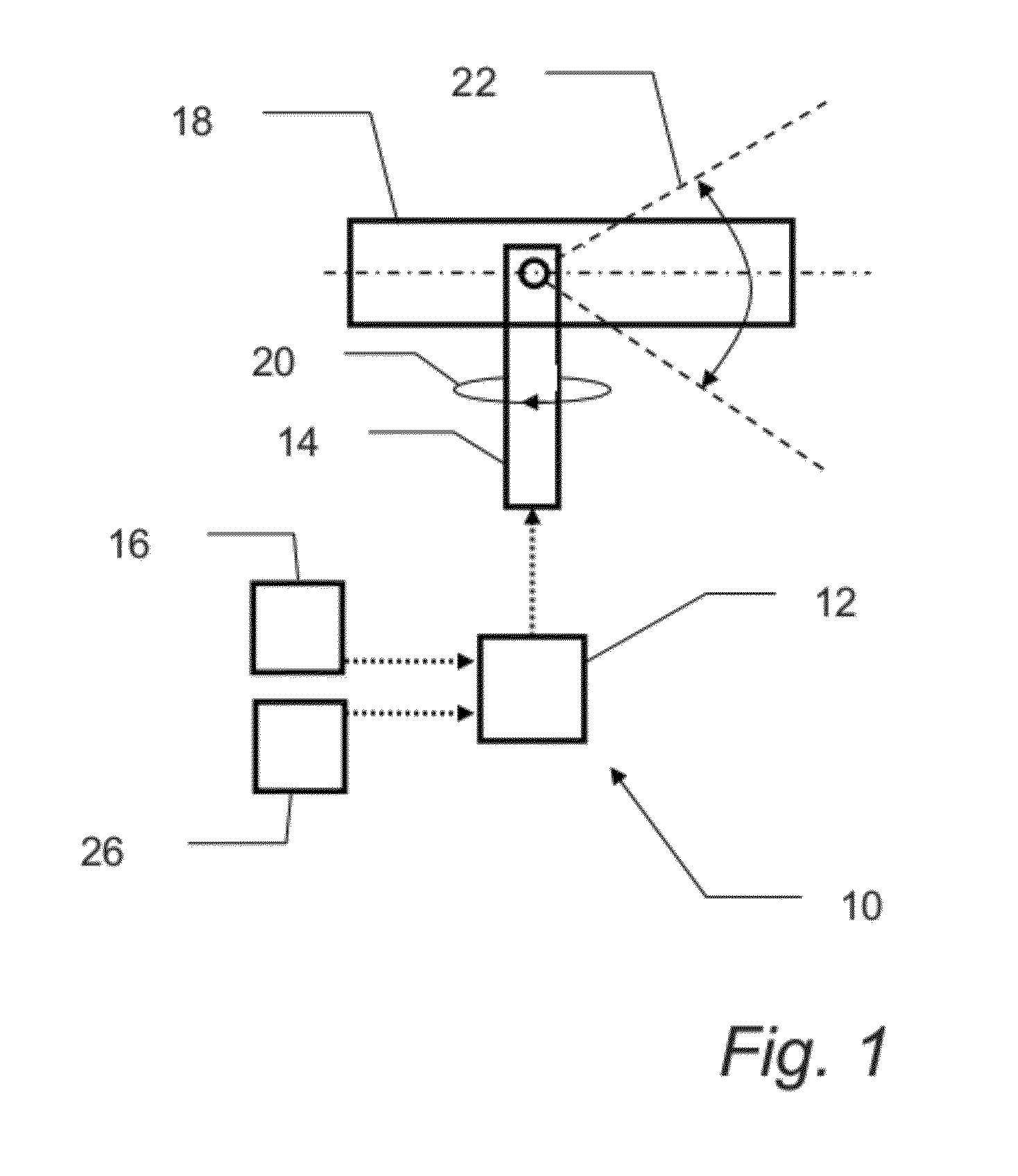
[0026]FIG. 1 is a block diagram illustrating a remote weapon system or station (RWS) 10 according to an embodiment of the present invention. The present RWS 10 will be described in the context of an automatic airburst retaliation system.

[0027]Basically, the RWS 10 comprises a fire control unit 12, a mechanical support 14, and an input means 16. Further, a weapon 18 is mounted to the mechanical support 14. The support 14 and weapon 18 are schematically shown in a side view in FIG. 1.

[0028]The mechanical support 14 is operably connected to the fire control unit 12. The mechanical support is adapted to move the weapon 18 is azimuth and elevation directions (indicated by 20 and 22, respectively) based on instructions from the fire control unit 12.

[0029]The input means 16 is also operably connected to the fire control unit 12. The input means 16 may for instance comprise a control grip through which an operator manually may provide input parameters to the fire control unit 12. Also, inpu...


PUM


Abstract

A remote weapon system (10) includes: a fire control unit (12); and a mechanical support (14) to which a weapon (18) capable of firing airburst ammunition is mountable, the mechanical support being adapted to move the weapon in azimuth and elevation directions. The fire control unit is adapted to receive input parameters including at least one area parameter related to a geographical area to be covered by the airburst ammunition from the weapon. Further, the fire control unit is configured to automatically calculate a number of shots of the weapon as well as azimuth and elevation directions of the mechanical support for each shot based on the input parameters such that substantially the entire geographical area is covered by the airburst ammunition when the weapon is fired.

Description

FIELD OF THE INVENTION[0001]The present invention relates to a remote weapon system, a fire control unit, an airburst control method, and a computer program product.BACKGROUND OF THE INVENTION[0002]An airburst or air burst is generally defined as the burst or detonation of a shell or bomb in the air instead of on contact with the ground or target.[0003]An airburst or airburst ammunition may be delivered or fired by a weapon mounted to a remote weapon system or station (RWS). An RWS is generally a remotely controlled weapon station for light and medium calibre weapons which can be installed on any type of vehicle or other platforms (land or sea-based).[0004]A prior art scenario for covering a specific grid or geographical area with airburst ammunition may involve an operator of the remote weapon station manually adjusting the remote weapon station in azimuth and elevation direction. The operator will fire the airburst ammunition, and try to cover the entire grid area. This may howeve...

Claims


Application Information

Patent Timeline
IPC IPC(8): G06G7/80
CPCF41A19/08F41A19/58F42B12/202F41G3/14F41G3/04
Inventor LAUPSTAD, KJELL M.WERNER, RUNEMALTERUD, EIRIKHAUGEN, LEIF O.
Owner KONGSBERG DEFENCE & AEROSPACE
Features
  • R&D
  • Intellectual Property
  • Life Sciences
  • Materials
  • Tech Scout
  • Unparalleled Data Quality
  • Higher Quality Content
  • 60% Fewer Hallucinations
Learn More