Multi-input bidirectional dc-dc converter

a dc-dc converter and multi-input technology, applied in the direction of dc-dc conversion, power conversion systems, instruments, etc., can solve the problems of power quality degradation, power grid instability, and difficulty in predicting the generation amount of energy

Inactive Publication Date: 2012-06-21
KOREA INST OF ENERGY RES
View PDF3 Cites 64 Cited by
  • Summary
  • Abstract
  • Description
  • Claims
  • Application Information

AI Technical Summary

Benefits of technology

[0009]In one general aspect, there is provided a multi-input bidirectional DC-DC converter including: a first bidirectional DC-DC converter including a first input unit which stores input current from a first energy storage module, a first primary half-bridge which is connected to the first input unit and controls the input current from the first energy storage module, an output unit which includes an output capacitor, a first secondary half-bridge which is connected to the output unit and controls the output voltage, and a first transformer whose primary side is connected to the first primary half-bridge, whose secondary side is connected to the first secondary half-bridge, and which transforms a voltage at the primary side or at the secondary side according to a power mode; and a n-th bidirectional DC-DC converter including a n-th input unit which stores input current from a n-th energy storage module, a n-th primary half-bridge which is connected to the n-th input unit and controls the input current from the n-th energy storage module, a n-th secondary half-bridge which is connected to the output unit of the first bidirectional DC-DC converter and controls the output voltage, and a n-th transformer whose primary side is connected to the n-th primary half-bridge, whose secondary side is connected to the n-th secondary half-bridge, and which transforms a voltage at the primary side or at the secondary si

Problems solved by technology

However, renewable energy, such as wind power or photovoltaic, greatly depends on climatic and geographical environments due to its intermittent output characteristics and accordingly has difficulties in predicting the generation amount of energy.
Because of these characte

Method used


Image

  • Multi-input bidirectional dc-dc converter
  • Multi-input bidirectional dc-dc converter
  • Multi-input bidirectional dc-dc converter

Examples


Embodiment Construction

[0017]The following description is provided to assist the reader in gaining a comprehensive understanding of the methods, apparatuses, and / or systems described herein. Accordingly, various changes, modifications, and equivalents of the methods, apparatuses, and / or systems described herein will be suggested to those of ordinary skill in the art. Also, descriptions of well-known functions and constructions may be omitted for increased clarity and conciseness.

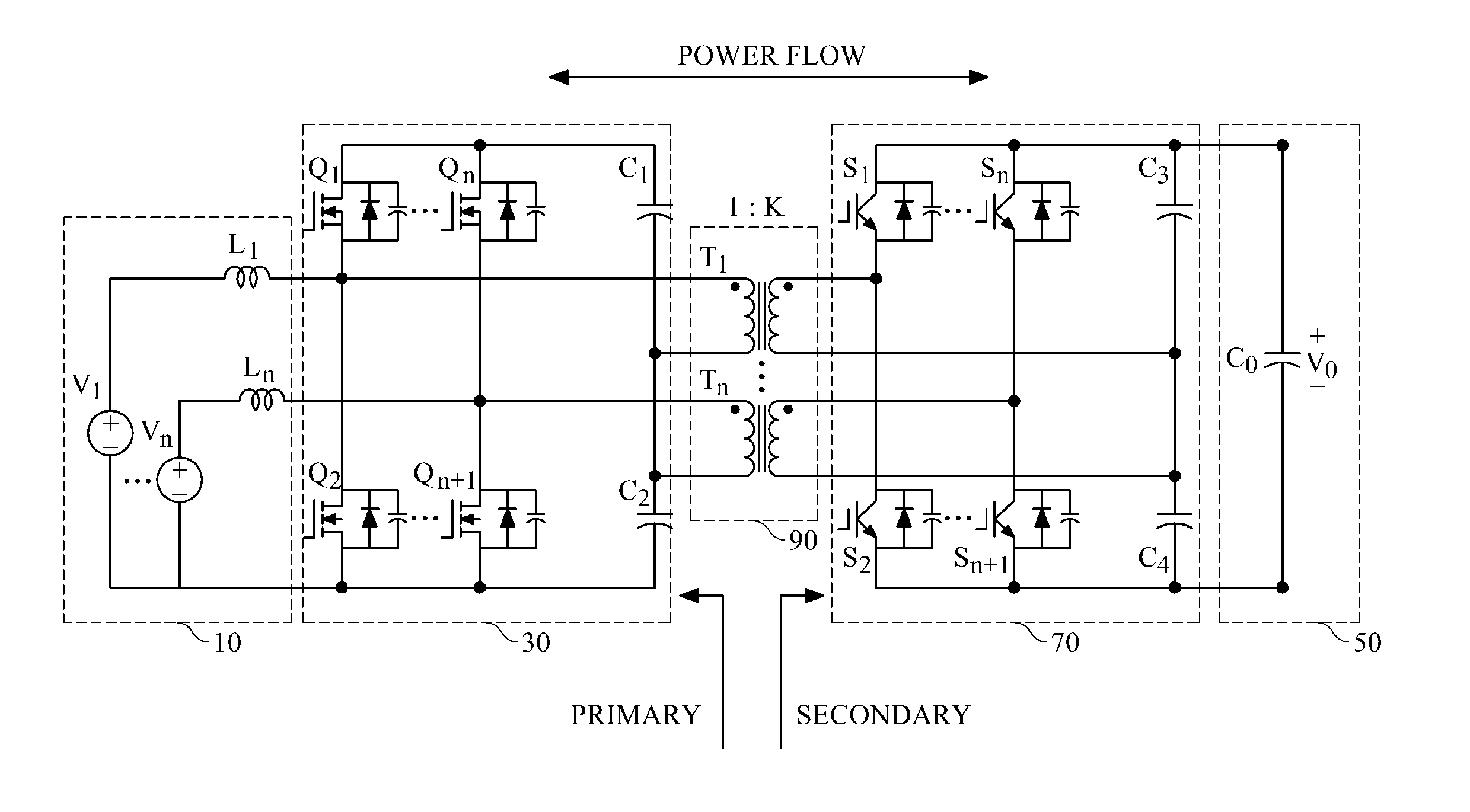
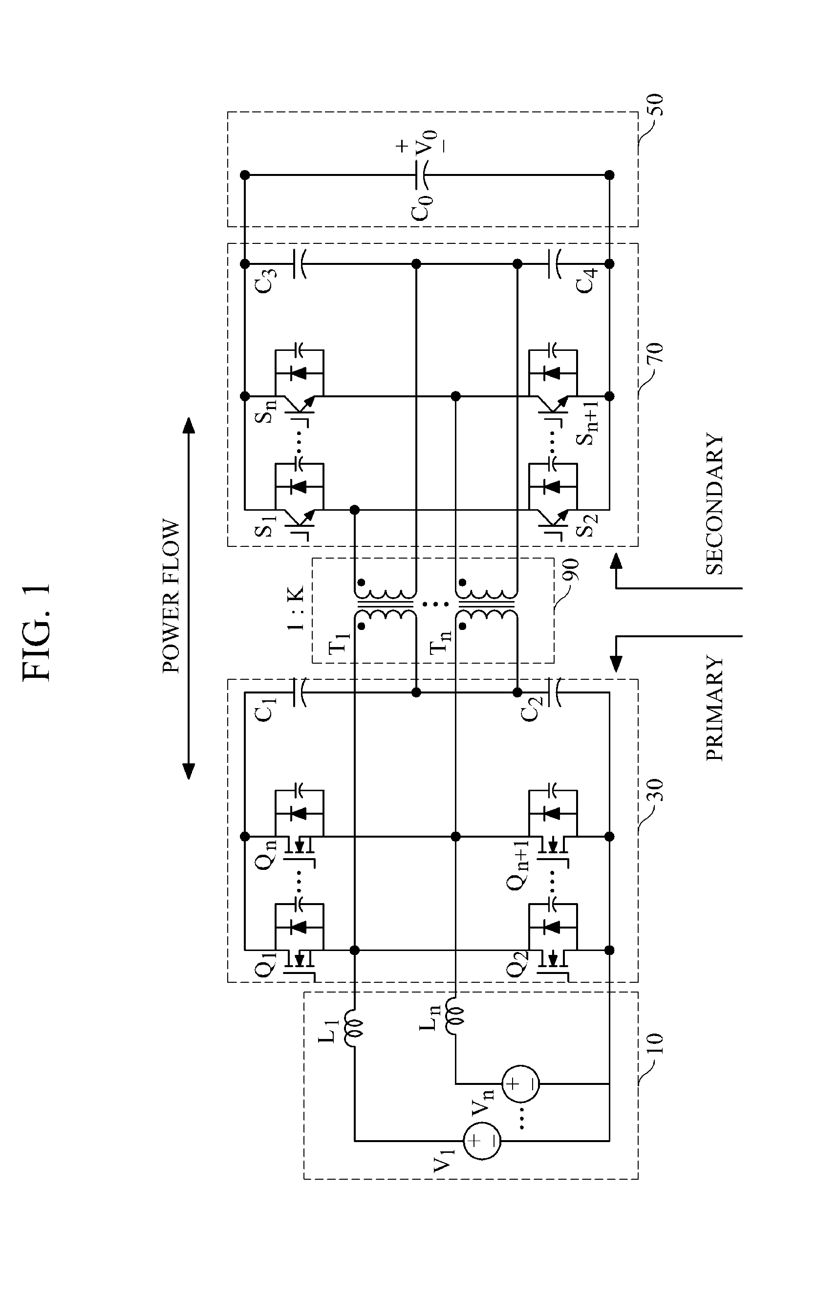
[0018]FIG. 1 is a circuit diagram illustrating an example of a multi-input bidirectional DC-DC converter.

[0019]Referring to FIG. 1, the multi-input bidirectional DC-DC converter includes two or more input units 10, two or more primary half-bridges 30, an output unit 50, two or more secondary half-bridges 70, and two or more transformers 90. In detail, the input units 10 include multiple energy storage modules V1, . . . , Vn and multiple input inductors L1, . . . , Ln connected respectively to the energy storage modules V1, . . . ,...


PUM


Abstract

Provided is technology for charge and discharge control of a plurality of energy storage modules having different properties. For achieving the technology, there is provided a multi-input bidirectional DC-DC converter including: a first bidirectional DC-DC converter including a first input unit which stores an input current from a first energy storage module, a primary-side first half-bridge which is connected to the first input unit and controls an input current from the first energy storage module, an output unit which includes an output capacitor, a secondary-side half-bridge which is connected to the output unit and controls the output voltage, and a first transformer whose primary side is connected to the primary-side first half-bridge, whose secondary side is connected to the secondary-side first half-bridge, and which transforms a voltage at the primary side or at the secondary side according to a power mode; and a n-th bidirectional DC-DC converter.

Description

CROSS-REFERENCE TO RELATED APPLICATION[0001]This application claims the benefit under 35 U.S.C. §119(a) of a Korean Patent Application No. 10-2010-0130283, filed on Dec. 17, 2010, the entire disclosure of which is incorporated herein by reference for all purposes.BACKGROUND[0002]1. Field[0003]The following description relates to a bidirectional DC-DC converter, and more particularly, to a multi-input bidirectional DC-DC converter with multiple energy storage modules.[0004]2. Description of the Related Art[0005]Renewable energy is currently being introduced worldwide to solve global warming and environmental pollution problems. However, renewable energy, such as wind power or photovoltaic, greatly depends on climatic and geographical environments due to its intermittent output characteristics and accordingly has difficulties in predicting the generation amount of energy. Because of these characteristics, distributed generation system using renewable energy may cause instability of po...

Claims


Application Information

Patent Timeline
IPC IPC(8): H02J1/00H02M3/335
CPCH02M3/33584H02J7/0013H02J2207/50
Inventor SONG, YUJINHAN, SOO-BINPARK, SUKINJEONG, HAK-GEUNCHAE, SU-YONGKIM, GYU-DUKYU, SEUNG-WEON
Owner KOREA INST OF ENERGY RES
Why Eureka
Try Eureka