Wireless energy transfer over distance using field shaping to improve the coupling factor

a technology of field shaping and wireless energy, applied in the direction of charging stations, electric devices, transportation and packaging, etc., can solve the problems of inability to transfer useful amounts of electrical energy, and inability to achieve effective electrical energy transfer

Active Publication Date: 2012-06-21
WITRICITY CORP
View PDF0 Cites 170 Cited by
  • Summary
  • Abstract
  • Description
  • Claims
  • Application Information

AI Technical Summary

Benefits of technology

[0014]In the wireless energy transfer systems we describe, remote devices may be powered directly, using the wirelessly supplied power or energy, or the devices may be coupled to an energy storage unit such as a battery, a super-capacitor, an ultra-capacitor, or the like (or other kind of power drain), where the energy storage unit may be charged or re-charged wirelessly, and / or where the wireless power transfer mechanism is simply supplementary to the main power source of the device. The devices may be powered by hybrid battery / energy storage devices such as batteries with integrated storage capacitors and the like. Furthermore, novel battery and energy storage devices may be designed to take advantage of the operational improvements enabled by wireless power transmission systems.

Problems solved by technology

However, this type of radiative transfer is very inefficient because only a tiny portion of the supplied or radiated power, namely, that portion in the direction of, and overlapping with, the receiver is picked up.
Such inefficient power transfer may be acceptable for data transmission, but is not practical for transferring useful amounts of electrical energy for the purpose of doing work, such as for powering or charging electrical devices.
However, these directed radiation schemes may require an uninterruptible line-of-sight and potentially complicated tracking and steering mechanisms in the case of mobile transmitters and / or receivers.
In addition, such schemes may pose hazards to objects or people that cross or intersect the beam when modest to high amounts of power are being transmitted.

Method used


Image

  • Wireless energy transfer over distance using field shaping to improve the coupling factor
  • Wireless energy transfer over distance using field shaping to improve the coupling factor
  • Wireless energy transfer over distance using field shaping to improve the coupling factor

Examples


examples

[0331

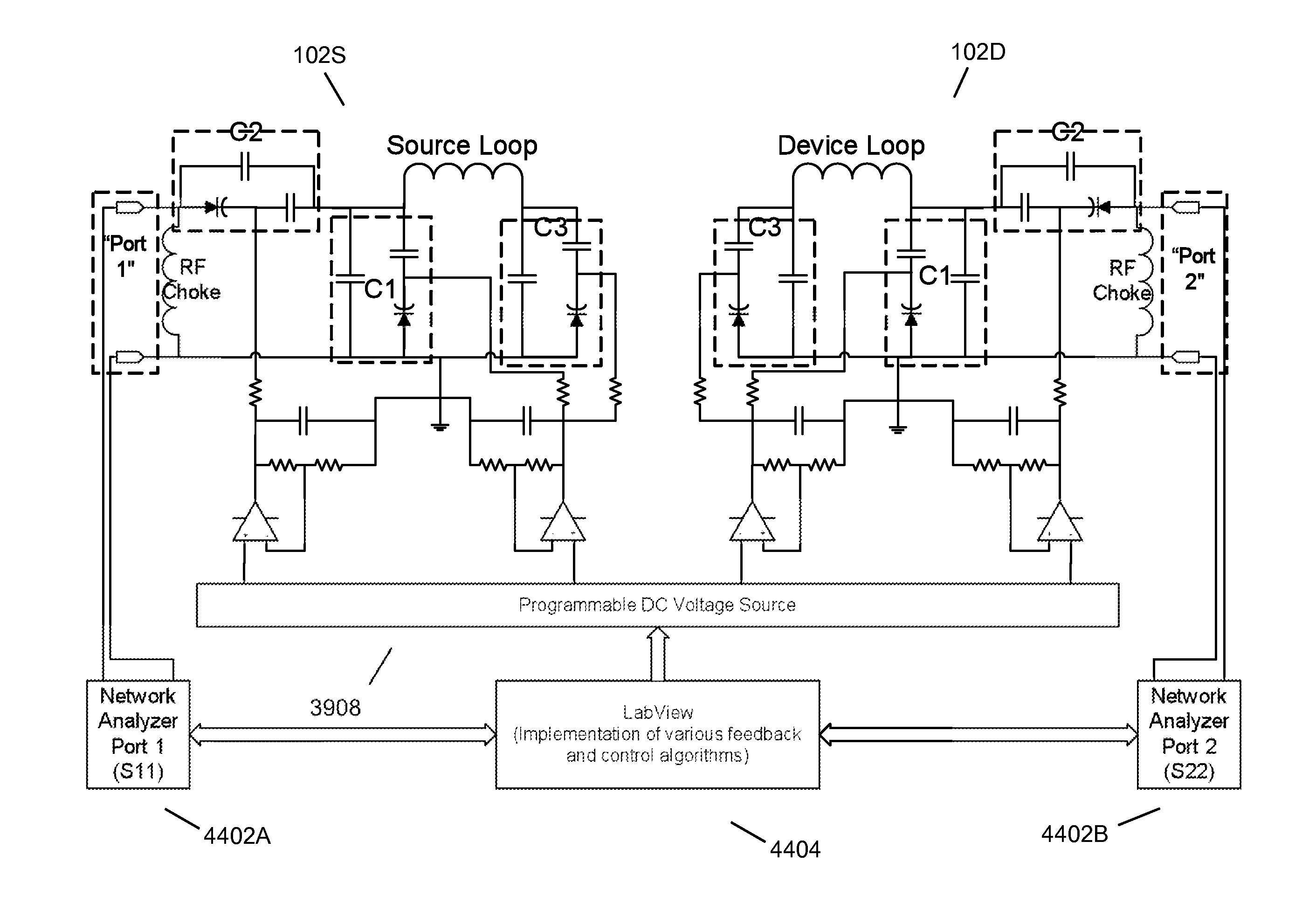
[0332]In the following schematics, we show different specific topology implementations for impedance matching to and resonator designs for a low-loss inductive element. In addition, we indicate for each topology: which of the principles described above are used, the equations giving the values of the variable elements that may be used to achieve the matching, and the range of the complex impedances that may be matched (using both inequalities and a Smith-chart description). For these examples, we assume that Z0 is real, but an extension to a characteristic impedance with a non-zero imaginary part is straightforward, as it implies only a small adjustment in the required values of the components of the matching network. We will use the convention that the subscript, n, on a quantity implies normalization to (division by) Z0.

[0333]FIG. 29 shows two examples of a transformer-coupled impedance-matching circuit, where the two tunable elements are a capacitor and the mutual inductance...


PUM


Abstract

In embodiments of the present invention improved capabilities are described for a method and system comprising a first resonator optionally coupled to an energy source and a second resonator located a variable distance from the source resonator and not connected by any wires to the first resonator, where the first resonator and the second resonator are coupled to provide near-field wireless energy transfer among the first resonator and the second resonator, and where the field of at least one of the first resonator and the second resonator is shaped to increase the coupling factor among the resonators.

Description

CROSS-REFERENCE TO RELATED APPLICATIONS[0001]This application is a continuation-in-part of the following U.S. patent application, U.S. Ser. No. 12 / 567,716 filed Sep. 25, 2009 which claims the benefit of the following U.S. provisional applications, U.S. App. No. 61 / 100,721 filed Sep. 27, 2008; U.S. App. No. 61 / 108,743 filed Oct. 27, 2008; U.S. App. No. 61 / 147,386 filed Jan. 26, 2009; U.S. App. No. 61 / 152,086 filed Feb. 12, 2009; U.S. App. No. 61 / 178,508 filed May 15, 2009; U.S. App. No. 61 / 182,768 filed Jun. 1, 2009; U.S. App. No. 61 / 121,159 filed Dec. 9, 2008; U.S. App. No. 61 / 142,977 filed Jan. 7, 2009; U.S. App. No. 61 / 142,885 filed Jan. 6, 2009; U.S. App. No. 61 / 142,796 filed Jan. 6, 2009; U.S. App. No. 61 / 142,889 filed Jan. 6, 2009; U.S. App. No. 61 / 142,880 filed Jan. 6, 2009; U.S. App. No. 61 / 142,818 filed Jan. 6, 2009; U.S. App. No. 61 / 142,887 filed Jan. 6, 2009; U.S. App. No. 61 / 156,764 filed Mar. 2, 2009; U.S. App. No. 61 / 143,058 filed Jan. 7, 2009; U.S. App. No. 61 / 152,390 ...

Claims


Application Information

Patent Timeline
Patent Type & Authority Applications(United States)
IPC IPC(8): H02J17/00
CPCB60L3/0069Y02T90/121B60L11/184B60L11/1842B60L11/1844B60L11/1846B60L11/1848B60L2210/10B60L2210/20B60L2210/30B60L2210/40B60L2230/22B60L2230/24B60L2250/10B60L2250/16B60L2270/32H02J5/005H03H7/40Y02T10/7088Y02T10/7005Y02T10/7241Y02T10/7216Y02T10/725Y02T90/163Y02T90/169Y02T90/14Y02T90/128Y02T90/127Y02T90/122Y04S10/126Y04S30/14Y02E60/721B60L2200/26B60L11/182B60L53/64B60L55/00B60L53/63B60L53/65B60L53/665B60L53/51B60L53/52B60L53/124B60L53/126H02J7/35Y02E60/00Y02T10/72Y02T10/7072Y02T10/70Y02T90/12Y02T90/167H02J50/90H02J50/50H02J50/80H02J50/12H02J50/70H02J50/20Y02T90/16
Inventor KARALIS, ARISTEIDISKURS, ANDRE B.CAMPANELLA, ANDREW J.KULIKOWSKI, KONRAD J.HALL, KATHERINE L.SOLJACIC, MARINKESLER, MORRIS P.
Owner WITRICITY CORP
Why Eureka
Try Eureka