
Lighting device, manufacturing method thereof, and electronic apparatus

a manufacturing method and light source technology, applied in the direction of electrical lighting sources, electroluminescent light sources, organic semiconductor devices, etc., can solve the problems of incomplete lighting devices, large defect in light emitting elements, and possible short circuit between two electrodes, so as to improve light utilization efficiency

Inactive Publication Date: 2012-06-21
ELEMENT CAPITAL COMMERCIAL CO PTE LTD
View PDF3 Cites 15 Cited by
  • Summary
  • Abstract
  • Description
  • Claims
  • Application Information

AI Technical Summary

Benefits of technology

[0008]Thus, an advantage of some aspects of the invention is to provide a lighting device in which a short circuit is prevented and which is able to perform stable light emitting.According to an aspect of the invention, there is provided a lighting device having a plurality of light emitting elements. The lighting device includes a first substrate, a supporting electrode to which a first source electric potential is supplied, a plurality of light emitting functional layers, a plurality of first electrodes, a second electrode to which a second source electric potential is supplied, a plurality of fuse units, each of the plurality of fuse units electrically connecting one of the first electrodes and the supporting electrode, an insulating first partitioning wall which separates each of the plurality of light emitting functional layers from each other, and separates each of the plurality of first electrodes from each of the plurality of light emitting elements, and an insulating second partitioning wall which separates each of the plurality of fuse units.

Problems solved by technology

However, when the light emitting functional layer deteriorates with time, or a conductive foreign substance enters the light emitting functional layer in the manufacturing process, there is a possibility of a short circuit occurring between the two electrodes.
In addition, when disconnection occurs in the lighting device, there is a problem in that in the lighting device in which the plurality of organic EL elements is connected in series, the entire lighting device is influenced by the disconnection and is turned off.
When it is assumed that the lighting device is formed of a single light emitting element, and when a part of the light emitting element is defective due to deterioration with time or entering of a foreign substance in the manufacturing process, the defect expands in the light emitting element, and the entire lighting device is unable to emit light.

Method used


Image

  • Lighting device, manufacturing method thereof, and electronic apparatus
  • Lighting device, manufacturing method thereof, and electronic apparatus
  • Lighting device, manufacturing method thereof, and electronic apparatus

Examples


first embodiment

A: First Embodiment

[0044]Hereinafter, various embodiments according to the invention will be described with reference to accompanying drawings. In the drawings, the ratio of a size of each unit will be appropriately differentiated from the real unit.

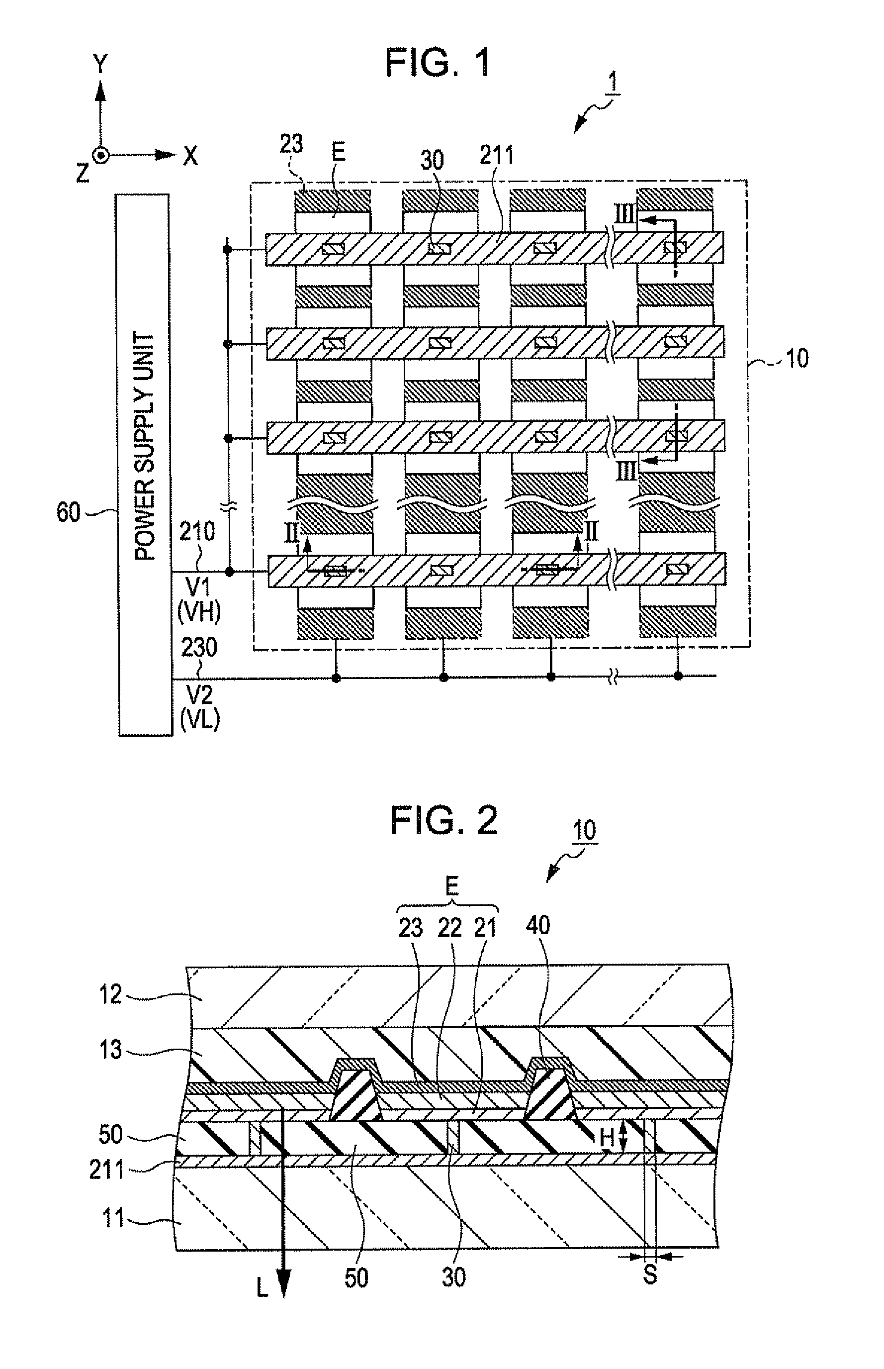
[0045]FIG. 1 is a plan view which shows a lighting device 1 according to an embodiment of the invention.

[0046]As shown in FIG. 1, the lighting device 1 includes a lighting unit 10 and a power supply unit 60.

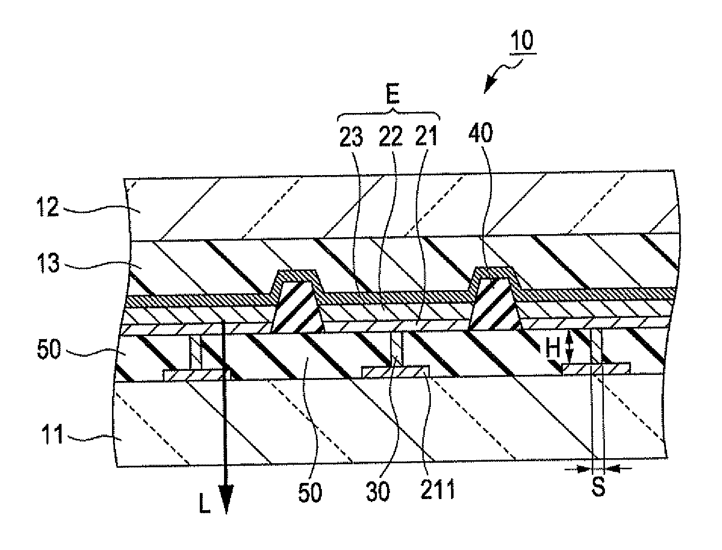
[0047]The lighting unit 10 is formed of M supporting electrodes 211 which extend in the X direction and N second electrodes 23 which extend in the Y direction which intersects the X direction, and light emitting elements E which correspond to intersections of the M supporting electrodes 211 and the N second electrodes 23, and are arranged in a matrix of vertical M rows x horizontal N rows (here, M and N are natural numbers of one or more).

[0048]A power supply unit 60 supplies a first electric potential V1 to the supporting electrode...

second embodiment

B: Second Embodiment

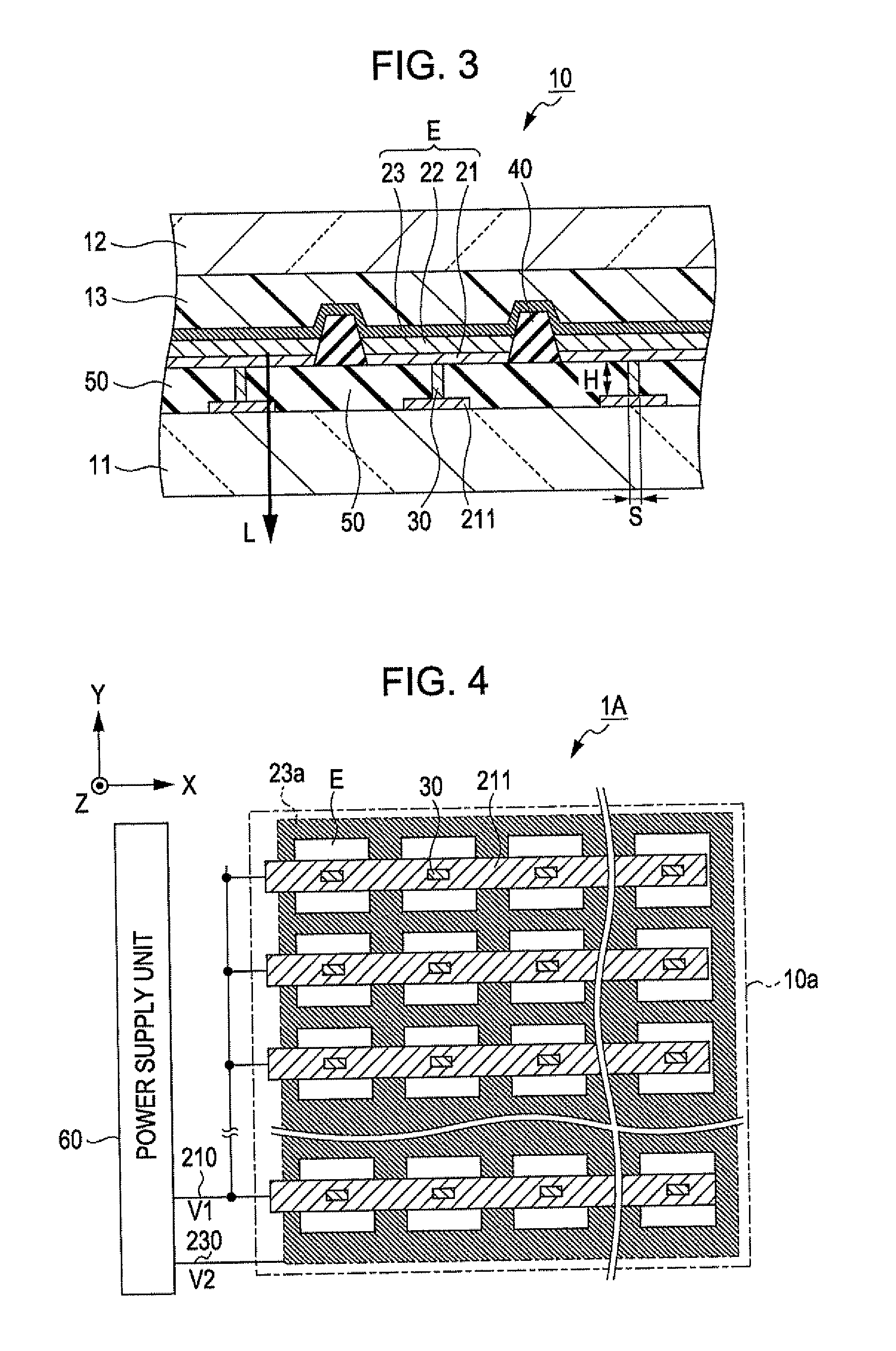
[0083]Lighting device 1B according to a second embodiment has the same configuration as that of the lighting device 1 according to the first embodiment, except that the lighting device 1B has a lighting unit 10b including a fuse unit 30b which is provided so as to be common with respect to the plurality of the light emitting elements E.

[0084]FIG. 5 is a plan view which shows the lighting device 1B according to the second embodiment. As shown in FIG. 5, the lighting device 1B has the lighting unit 10b which includes the fuse unit 30b which is commonly provided with respect to two neighboring light emitting elements E which are provided corresponding to the same supporting electrode 211.

[0085]FIG. 6 is a cross-sectional view of the lighting device 1B shown in FIG. 5 which is cut along line VI-VI. As shown in FIG. 6, the fuse unit 30b is provided on the supporting electrode 211, and is electrically connected to two neighboring first electrodes 21 and the supportin...

third embodiment

C: Third embodiment

[0093]Lighting device 1D according to a third embodiment has the same configuration as that of the lighting device 1 according to the first embodiment, except that a fuse unit 30d is provided on a second substrate side, a first electrode 21d is provided on the second substrate side of a light emitting functional layer 22 and functions as a cathode, a second electrode 23d is provided on a first substrate side of the light emitting functional layer 22 and functions as an anode.

[0094]FIG. 8 is a plan view which shows the lighting device 1D according to the third embodiment. As shown in FIG. 8, the lighting device 1D has a lighting unit 10d. In the lighting unit 10d, M second electrodes 23d which extend in the X direction, N supporting electrodes 211d which extend in the Y direction which intersects the X direction, and light emitting elements E which are arranged in matrix of vertical M rows x horizontal N rows (M and N are natural numbers of one or more) are forme...


PUM


Abstract

A lighting unit includes, a plurality of light emitting elements which has a first substrate, a supporting electrode, light emitting functional layers, first electrodes, and a second electrode; a plurality of fuse units,; an insulating first partitioning wall which separates each of the light emitting functional layers from each other, and each of the first electrodes from each other; and an insulating second partitioning wall which separates each of fuse units from each other. One of the plurality of fuse units electrically connects one of the first electrodes and the supporting electrode.

Description

BACKGROUND[0001]1. Technical Field[0002]The present invention relates to a lighting device which includes a luminous element such as an organic EL (Electroluminescence) element or the like, the manufacturing method thereof, and an electronic apparatus including the device.[0003]2. Related Art[0004]In recent years, a lighting device which includes an organic EL element has been developed. Since the thickness of the light-emitting layer of the organic EL element, which is a self-luminous element, is extremely thin, it is possible to make the lighting device light and thin when the organic EL element is applied to the lighting device. In addition, since the organic EL element is able to emit light of high luminance in a low voltage, it is also possible to achieve power savings in the lighting device. In this manner, since it is possible to make the lighting device in which the organic EL element is used thin and be able to save electric power, the lighting device may be also mounted in...

Claims


Application Information

Patent Timeline
IPC IPC(8): H05B37/02H05B44/00
CPCH01L51/5203H01L2251/5392H01L2251/5361H10K2102/341H10K59/805H10K50/805
Inventor KASAI, TOSHIYUKI
Owner ELEMENT CAPITAL COMMERCIAL CO PTE LTD
Features
  • Generate Ideas
  • Intellectual Property
  • Life Sciences
  • Materials
  • Tech Scout
  • Unparalleled Data Quality
  • Higher Quality Content
  • 60% Fewer Hallucinations
Learn More