
Light timeout optimization

a technology of timeout and lamp, applied in the field of lighting, can solve problems such as the reduction of achieve the effect of reducing the timeout value of the lamp

Active Publication Date: 2012-06-21
WTEC GMBH
View PDF9 Cites 90 Cited by
  • Summary
  • Abstract
  • Description
  • Claims
  • Application Information

AI Technical Summary

Benefits of technology

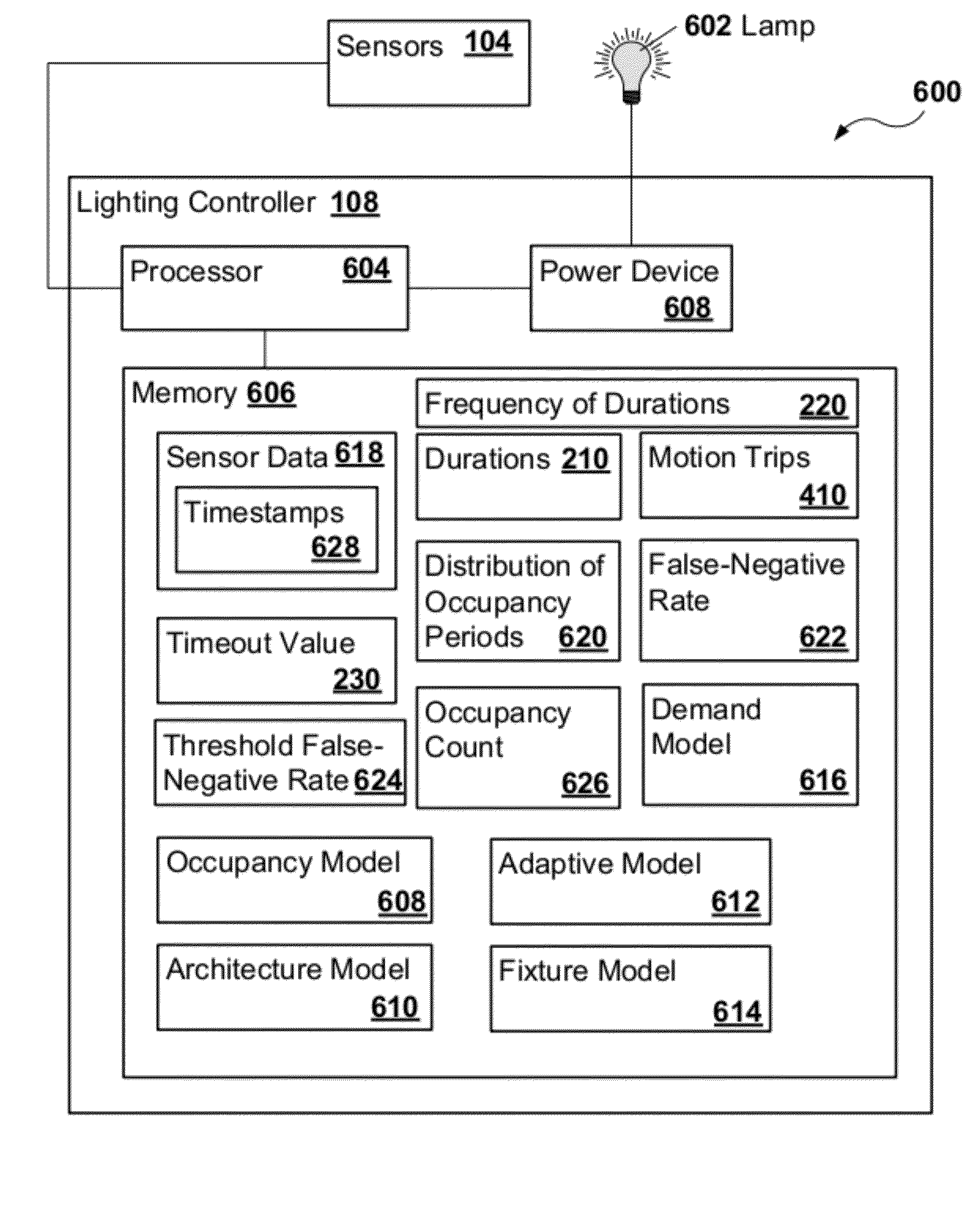
[0005]A lighting controller may be provided for optimizing a timeout value of a lamp that illuminates a lighting area. The lighting controller may include a memory, an occupancy model, and a demand model. The memory may include sensor data. The occupancy model may determine a false-negative rate for the lamp from the sensor data. The false-negative rate may include a frequency at which the lamp is timed out when the lighting area is occupied. The demand model may increase the timeout value of the lamp in response to the false-negative rate being above a threshold false-negative rate. Furthermore, the demand model may decrease the timeout value of the lamp in response to the false-negative rate being below the threshold false-negative rate.
[0006]A tangible non-transitory computer-readable medium may be provided that is encoded with computer executable instructions to optimize a timeout value of a lamp that illuminates a lighting area. The instructions, when executed, may determine a false-negative rate for the lamp from sensor data, where the false-negative rate is a frequency at which the lamp is timed out when the lighting area is occupied. The timeout value of the lamp may be increased in response to a determination that the false-negative rate is above a threshold false-negative rate. The timeout value of the lamp may be decreased in response to a determination that the false-negative rate is below the threshold false-negative rate.

Problems solved by technology

Furthermore, the demand model may decrease the timeout value of the lamp in response to the false-negative rate being below the threshold false-negative rate.

Method used


Image

  • Light timeout optimization
  • Light timeout optimization
  • Light timeout optimization

Examples


Embodiment Construction

1. Lighting System.

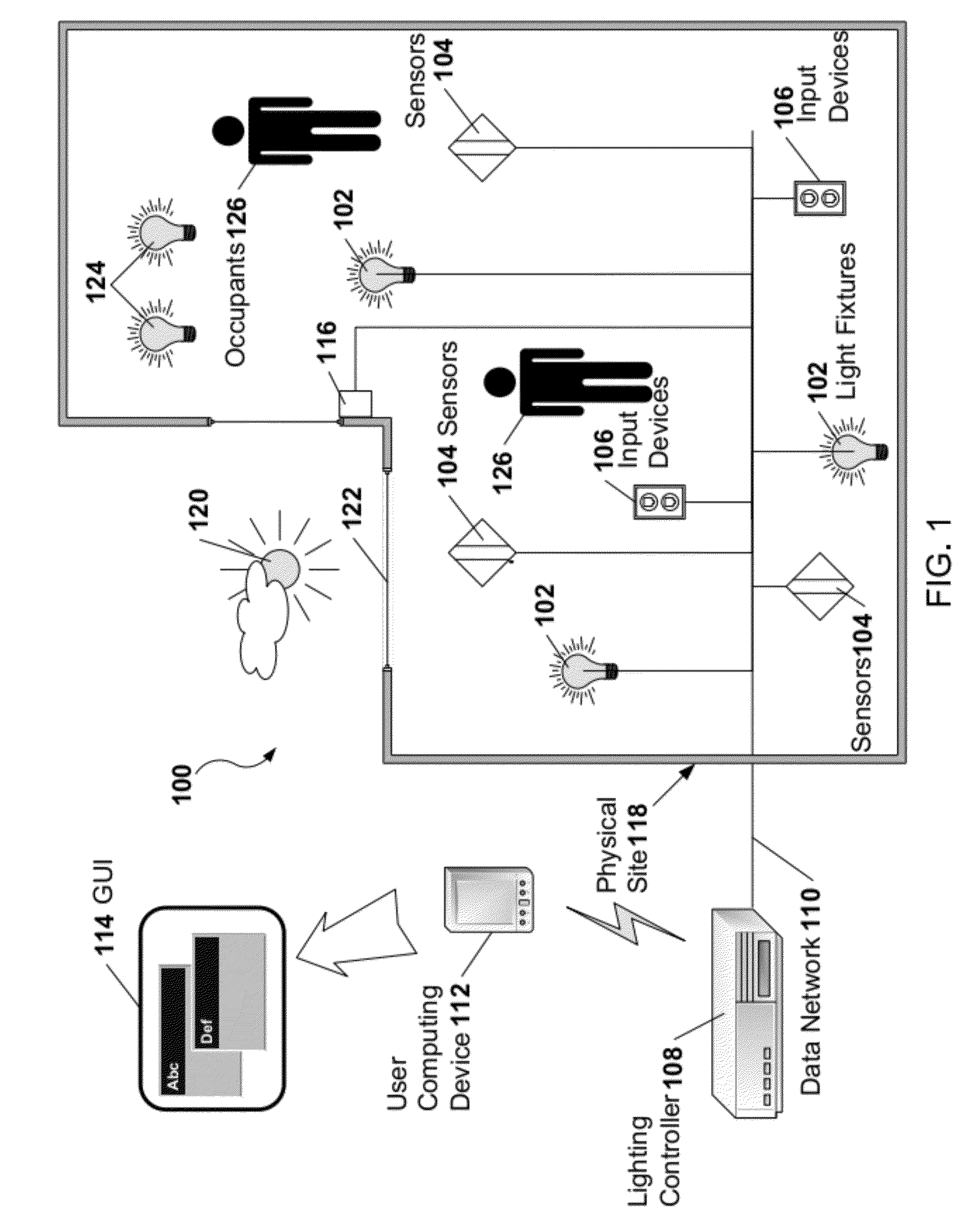
[0019]A lighting system may include light fixtures that provide light to a physical site or multiple sites. A control system may interpret, control, and learn aspects of the operation of the light system based on management goals set by an operator or user. In one example, the lighting system may include the control system. In a second example, the two systems may be physically separate from each other. In a third example, the lighting and control systems may be intermixed.

[0020]The lighting system, the control system, or both may be capable of controlling one or more small residential buildings, such as single-family homes, and one or more large commercial sites, such as office buildings, building campuses, factories, warehouses, and retail stores. The lighting system may control and obtain sensor data at rather high degrees of spatial resolution, such as receiving sensor data from each individual light fixture. Alternatively or in addition, one lighting area lit...


PUM


Abstract

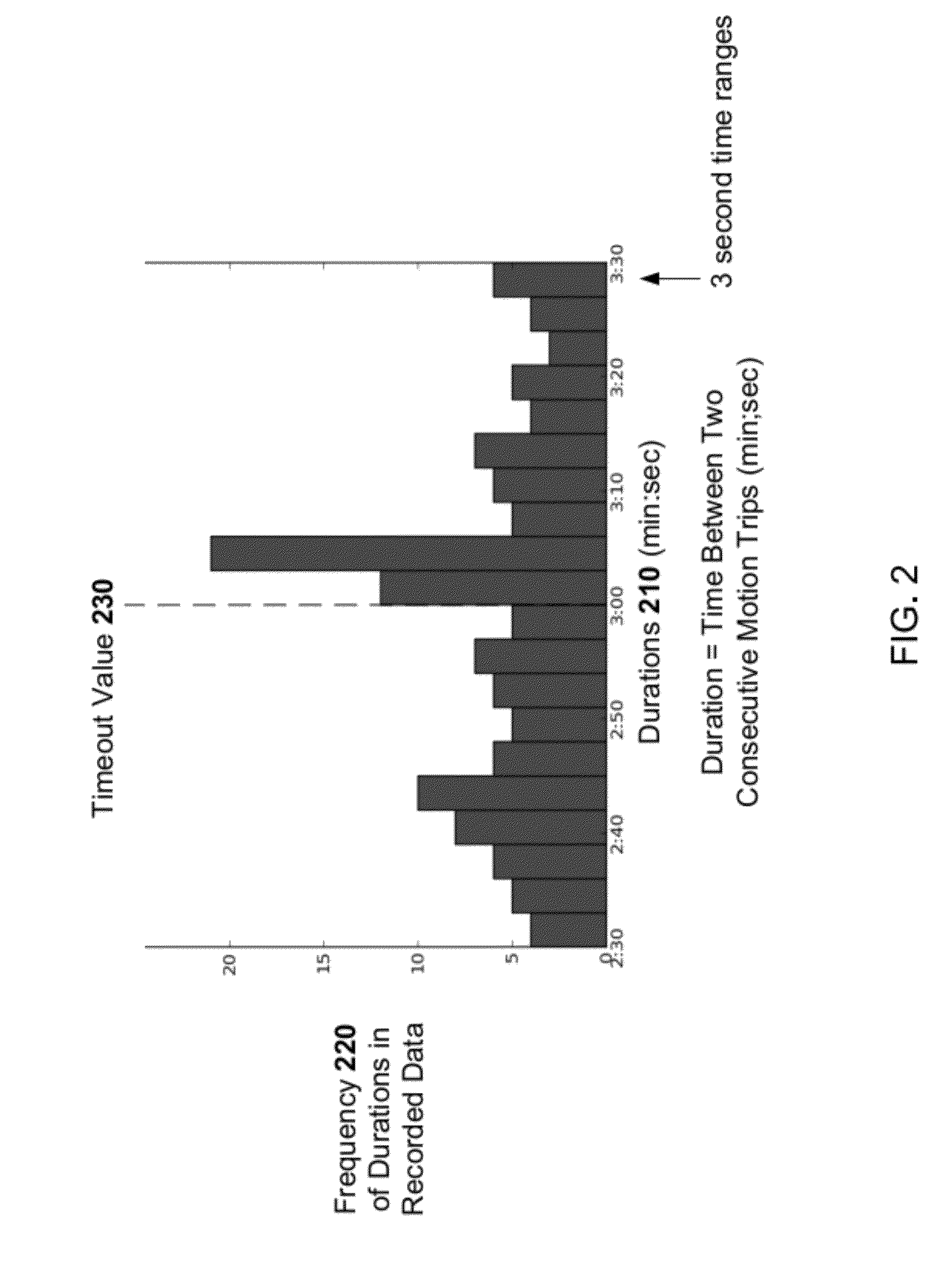
A lighting controller may optimize a timeout value of a lamp based on the goals of saving energy and providing occupant comfort. The lamp may illuminate a lighting area. The lighting controller may determine a false-negative rate for the lamp from sensor data that represents a frequency at which the lamp is timed out while the lighting area is occupied. The lighting controller may adjust the timeout value of the lamp over time so that the false-negative rate approaches a threshold false-negative rate. The false-negatives and occupancy periods may be detected from spikes in time distributions of motion data. The amount of energy that the lamp would consume at an increased timeout value of the lamp may be determined from motion data stored while the timeout value of the lamp is at an initial timeout value.

Description

BACKGROUND[0001]1. Technical Field[0002]This application relates to lighting and, in particular, to light timeouts.[0003]2. Related Art[0004]An occupancy sensor may detect whether an area is occupied. A device may switch off lights if the occupancy sensor indicates that the area is not occupied. The device may switch on lights if the occupancy sensor indicates that the area is occupied.SUMMARY[0005]A lighting controller may be provided for optimizing a timeout value of a lamp that illuminates a lighting area. The lighting controller may include a memory, an occupancy model, and a demand model. The memory may include sensor data. The occupancy model may determine a false-negative rate for the lamp from the sensor data. The false-negative rate may include a frequency at which the lamp is timed out when the lighting area is occupied. The demand model may increase the timeout value of the lamp in response to the false-negative rate being above a threshold false-negative rate. Furthermor...

Claims


Application Information

Patent Timeline
IPC IPC(8): H05B37/02
CPCY02B20/40H05B37/0227H05B47/115H05B47/13
Inventor GU, XINGU, KELVINNULU, DEEPAK
Owner WTEC GMBH
Learn More