
Apparatus and method for influencing and/or detecting magnetic particles in a field of view

a magnetic particle and apparatus technology, applied in the field of apparatus and corresponding methods for detecting magnetic particles in a field of view, can solve the problems that the mpi apparatus and the corresponding methods are still not optimal, and the spectral response of the magnetic nanoparticle may be delocalized and low, so as to improve the quality of reconstructed images and facilitate encoding and reconstruction.

Active Publication Date: 2012-06-21
KONINKLIJKE PHILIPS ELECTRONICS NV
View PDF4 Cites 14 Cited by
  • Summary
  • Abstract
  • Description
  • Claims
  • Application Information

AI Technical Summary

Benefits of technology

[0010]It is an object of the present invention to provide an apparatus and a corresponding method for influencing and / or detecting magnetic particles in a field of view by which the quality of reconstructed images is improved. Especially, artifacts in reconstructed images arising from low frequency components shall be avoided. Preferably, the proposed apparatus and method still shall allow a quick and easy encoding and reconstruction of an image of an object of interest.

Problems solved by technology

In certain situations problems may occur arising from delocalized low spectral components of the spectral response of the magnetic nanoparticles.
The above-mentioned problems also may arise in case of leaving out sub-volumes of the field of view for speeding up the encoding process, wherein such sub-volumes are left out that cover areas which are not of interest to the operator of the MPI apparatus or MPI scanner.
Because of the above described artifacts occurring in certain situations in reconstructed images existing MPI apparatuses and corresponding methods are still not optimal.

Method used


Image

  • Apparatus and method for influencing and/or detecting magnetic particles in a field of view
  • Apparatus and method for influencing and/or detecting magnetic particles in a field of view
  • Apparatus and method for influencing and/or detecting magnetic particles in a field of view

Examples


Embodiment Construction

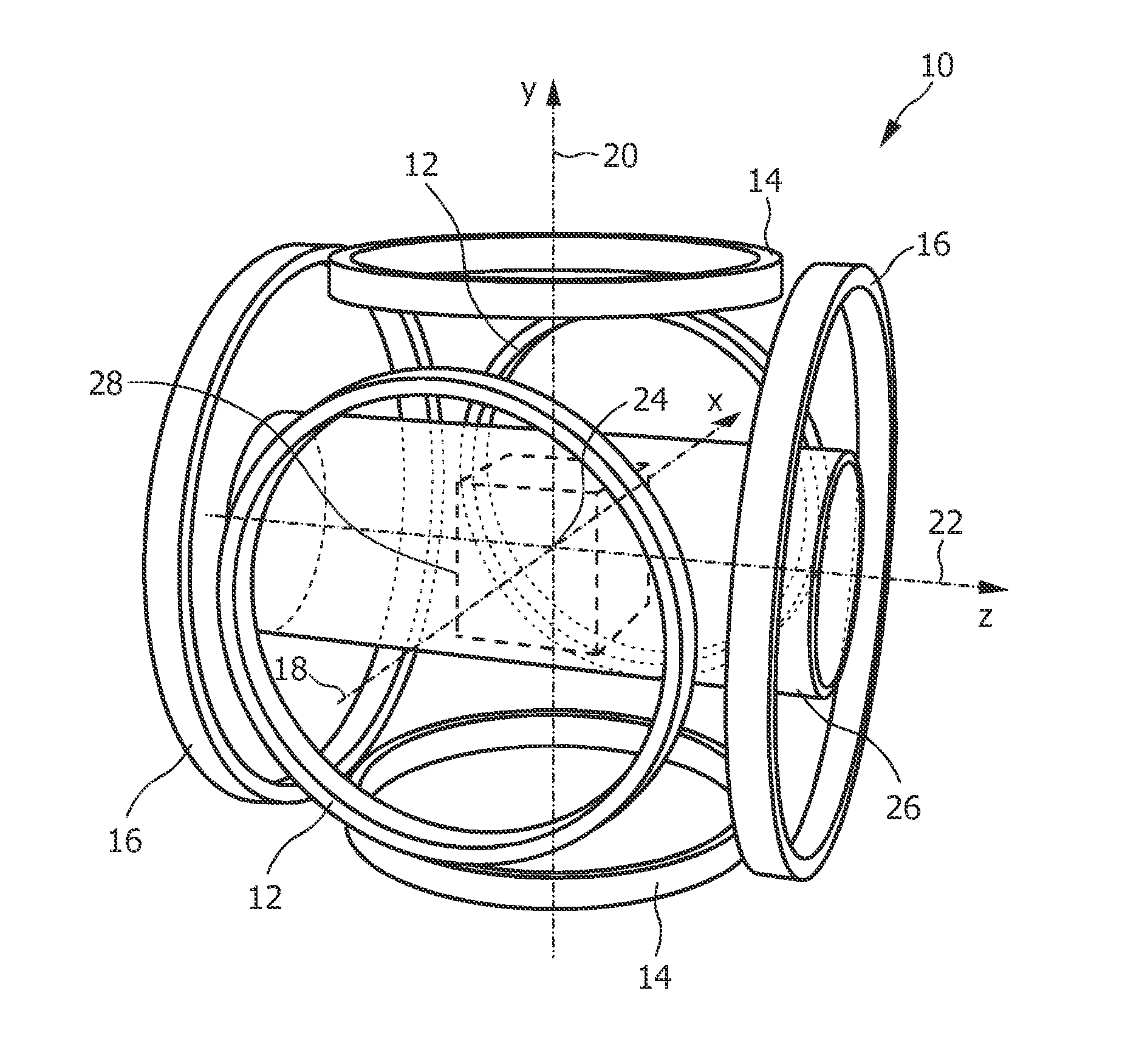
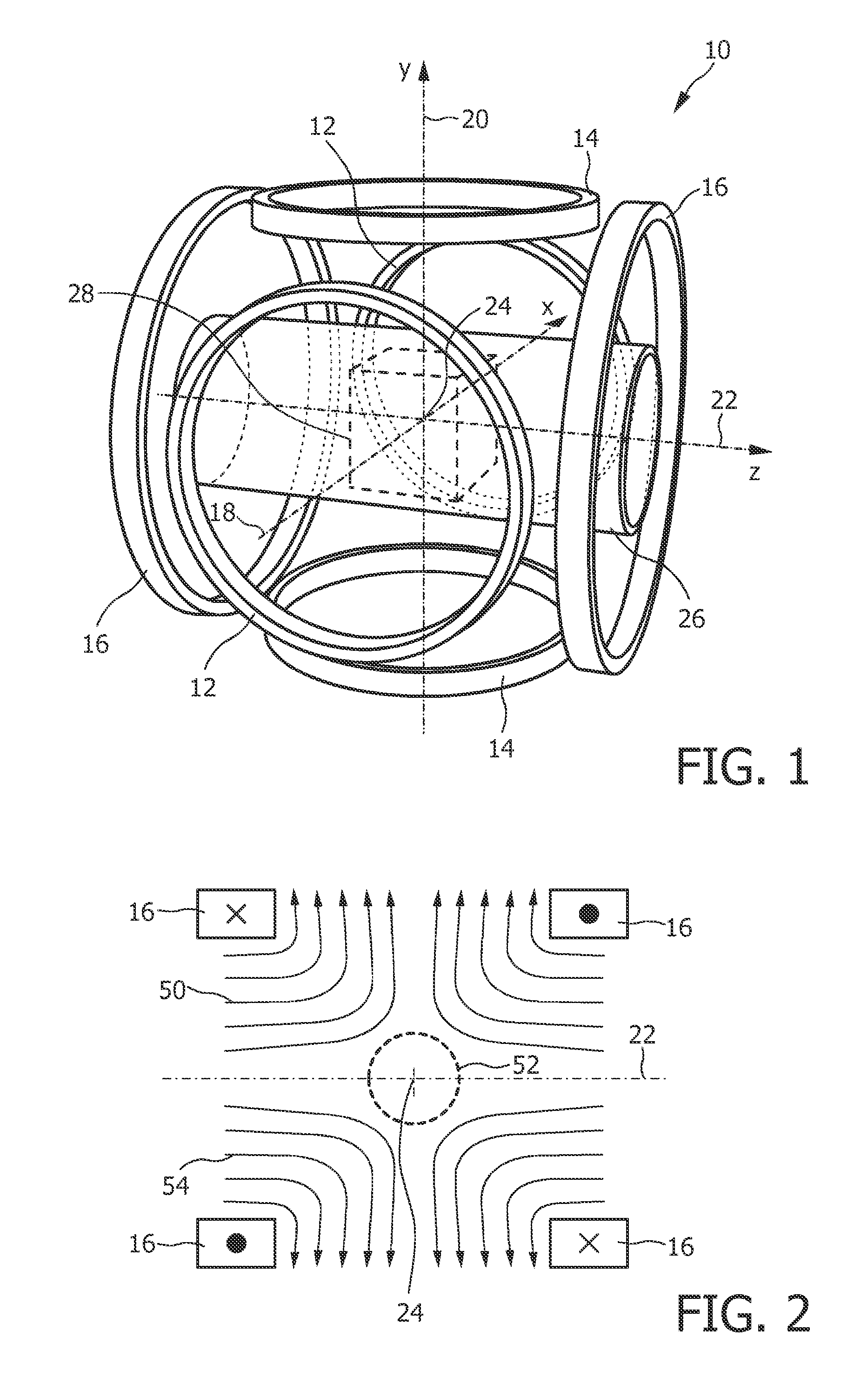
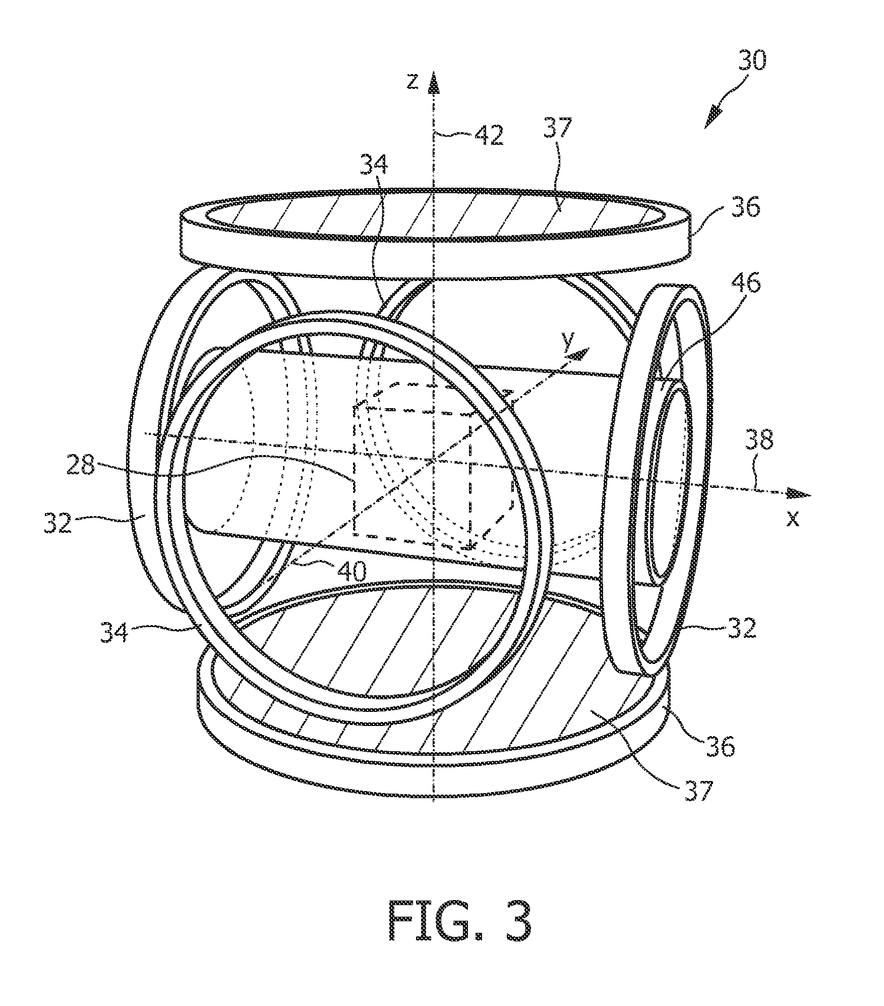
[0058]Before the details of the present invention shall be explained, basics of magnetic particle imaging shall be explained in detail with reference to FIGS. 1 to 4. In particular, two embodiments of an MPI scanner for medical diagnostics will be described. An informal description of the data acquisition is also given. The similarities and differences between the two embodiments will be pointed out.

[0059]The first embodiment 10 of an MPI scanner shown in FIG. 1 has three prominent pairs 12, 14, 16 of coaxial parallel circular coils, each pair being arranged as illustrated in FIG. 1. These coil pairs 12, 14, 16 serve to generate the selection field as well as the drive and focus fields. The axes 18, 20, 22 of the three coil pairs 12, 14, 16 are mutually orthogonal and meet in a single point, designated the isocenter 24 of the MPI scanner 10. In addition, these axes 18, 20, 22 serve as the axes of a 3D Cartesian x-y-z coordinate system attached to the isocenter 24. The vertical axis ...


PUM


Abstract

The present invention relates to an apparatus (100) for influencing and / or detecting magnetic particles in a field of view (28), wherein the field of view (28) comprises at least one sub field of interest covering at least a portion of an object of interest containing magnetic particles. The apparatus (100) applying the known principle of Magnetic Particle Imaging (MPI) comprises selection means for generating a magnetic selection field (50) having the known field pattern showing a field free point (FFP), drive means for changing the position in space of the FFP by means of a magnetic drive field, receiving means for acquiring detection signals depending on the magnetization of the magnetic particles within the field of view (28), a control unit (150) for controlling a signal receiving unit (140) comprised in the receiving means for acquiring a set of high resolution detection signals and a set of low resolution detection signals, wherein the set of high resolution detection signals depends on the magnetization of at least one subfield of interest and the set of low resolution detection signals depends on the magnetization of at least one adjacent subfield being arranged adjacent to the at least one subfield of interest, and a reconstruction unit (152) for reconstructing a particle distribution quantity depending on the set of high resolution detection signals and the set of low resolution detection signals. The present invention further relates to a corresponding method as well as to a computer program.

Description

FIELD OF THE INVENTION[0001]The present invention relates to an apparatus and a corresponding method for influencing and / or detecting magnetic particles in a field of view. Further, the present invention relates to a computer program for implementing said method on a computer and for controlling such an apparatus.BACKGROUND OF THE INVENTION[0002]“Magnetic Particle Imaging” (MPI) is an emerging medical imaging modality. The first versions of MPI were two-dimensional in that they produced two-dimensional images. Future versions will be three-dimensional (3D). A time-dependent, or 4D, image of a non-static object can be created by combining a temporal sequence of 3D images to a movie, provided the object does not significantly change during the data acquisition for a single 3D image.[0003]MPI is a reconstructive imaging method, like Computed Tomography (CT) or Magnetic Resonance Imaging (MRI). Accordingly, a MP image of an object's volume of interest is generated in two steps. The firs...

Claims


Application Information

Patent Timeline
Patent Type & Authority Applications(United States)
IPC IPC(8): G01R33/44
CPCA61B5/0515A61B5/05
Inventor RAHMER, JURGEN ERWINGLEICH, BERNHARDWEIZENECKER, JURGEN
Owner KONINKLIJKE PHILIPS ELECTRONICS NV
Learn More