Wireless Signal Transceiver and Blind Spot Detection System

a transceiver and wireless technology, applied in the direction of instruments, measurement devices, using reradiation, etc., can solve the problem of extremely limited available spa

Inactive Publication Date: 2012-06-21
WISTRON NEWEB
View PDF14 Cites 67 Cited by
  • Summary
  • Abstract
  • Description
  • Claims
  • Application Information

AI Technical Summary

Benefits of technology

[0009]The present invention discloses a wireless signal transceiver for a blind spot detection system, including a first substrate, a radio-frequency processing unit formed on the first substrate for transmitting a wireless signal and receiving a reflecting signal of the transmitted wireless signal, and a complex programmable logic device controlled by a digital signal processor for controlling operations of the radio-frequency processing unit according to at least one control command of the digital signal processor, so as to detect whether an object exists within a specific range.
[0010]The present invention further discloses a blind spot detection system, including a plurality of alarms, each for generating an alarm signal, a control host, for respectively controlling each of the plurality of alarms to generate a corresponding alarm signal according to a plurality of signal processing results, a plurality of wireless signal transceivers, a first wireless signal transceiver of the plurality of wireless signal transceivers including a first substrate, a radio-frequency processing unit, formed on the first substrate, for transmitting a wireless signal and receiving a reflecting signal of the transmitted wireless signal, and a complex programmable logic device, for controlling operations of the radio-frequency processing unit according to at least one control command, so as to detect whether an object exists within a specific range, and a digital signal processor, for outputting the at least one control command to control operations of the first wireless signal transceiver, and generating a signal processing result of the plurality of signal processing results according to a detection result generated by the complex programmable logic device of the first wireless signal transceiver.

Problems solved by technology

Since shock-absorbing Styrofoam or reinforcement bar is installed in the vehicle bumpers, available space is extremely limited.

Method used


Image

  • Wireless Signal Transceiver and Blind Spot Detection System
  • Wireless Signal Transceiver and Blind Spot Detection System
  • Wireless Signal Transceiver and Blind Spot Detection System

Examples


Embodiment Construction

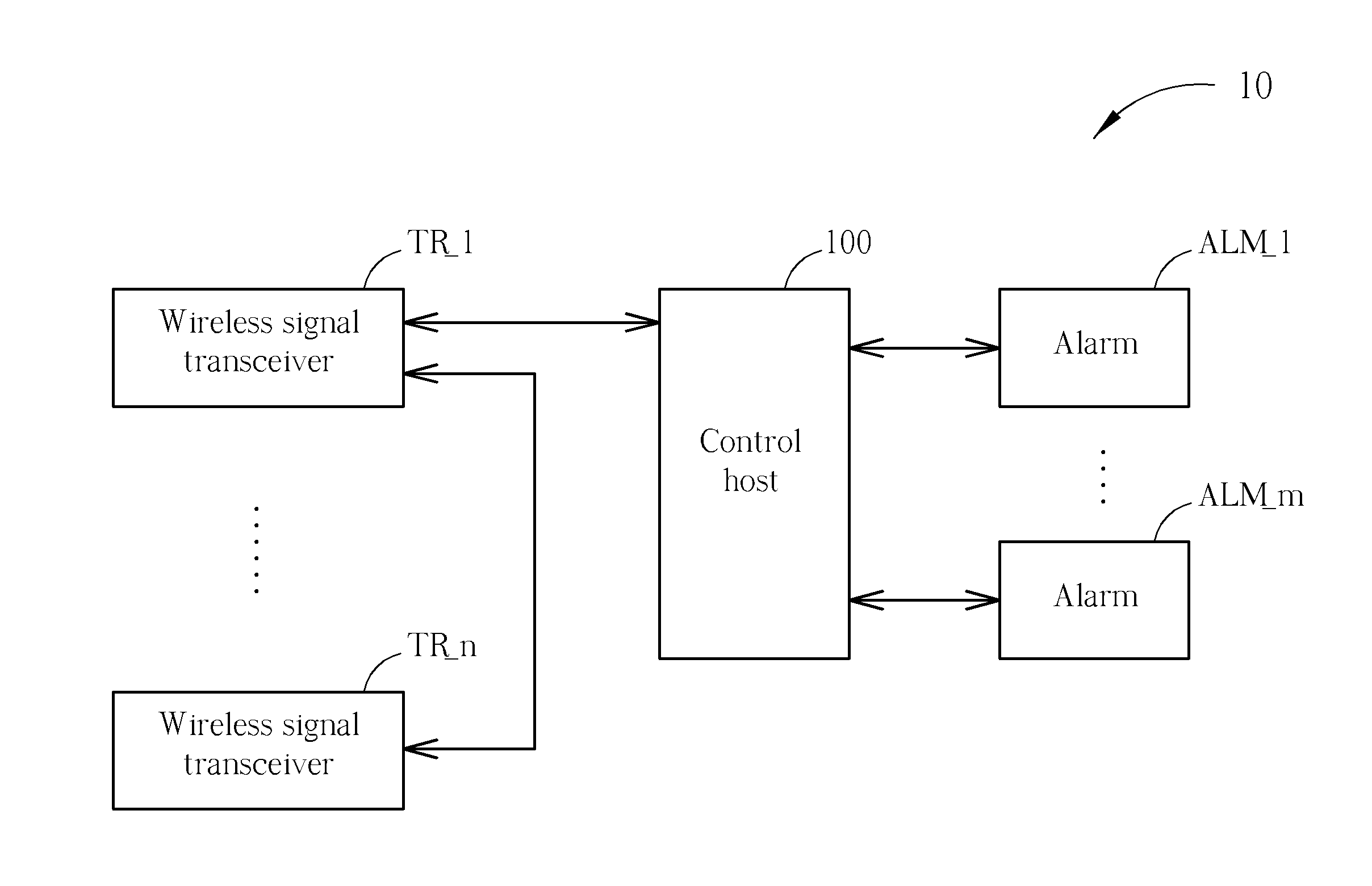
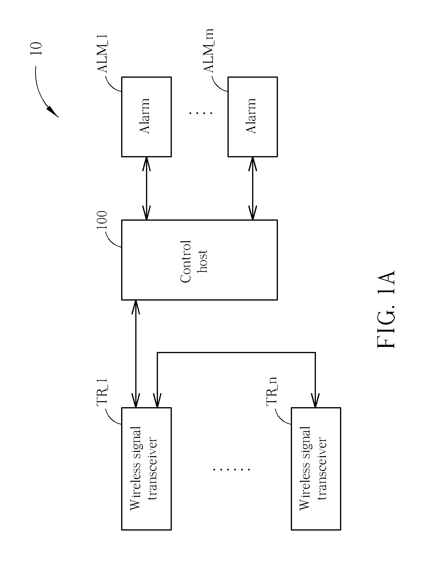
[0020]Please refer to FIG. 1A, which is a blind spot detection system 10 according to an embodiment of the present invention. The blind spot detection system 10 is installed in a vehicle, for detecting whether obstacles such as cars, humans, etc., are within specific blind spots, and outputting alarm signals accordingly, in order to avoid occurrence of a traffic accident caused by negligence or blind spot of a driver. The blind spot detection system 10 includes a control host 100, wireless signal transceivers TR_1-TR_n, and alarms ALM_1-ALM_m. The wireless signal transceivers TR_1-TR_n are installed in a rear (and / or front) bumper of the vehicle, and utilize radar sensing technology to detect whether obstacles exist in the blind spots of the driver. The wireless signal transceiver TR_1 is a primary wireless signal transceiver, which gathers data of the wireless signal transceivers TR_2-TR_n, and transmits the data to the control host 100. The control host 100 controls operations of ...


PUM


Abstract

A wireless signal transceiver for a blind spot detection system includes a first substrate, a radio-frequency processing unit formed on the first substrate for transmitting a wireless signal and receiving a reflecting signal of the transmitted wireless signal, and a complex programmable logic device controlled by a digital signal processor for controlling operations of the radio-frequency processing unit according to at least a control command of the digital signal processor, so as to detect whether an object exists within a specific range.

Description

BACKGROUND OF THE INVENTION[0001]1. Field of the Invention[0002]The present invention relates to a wireless signal transceiver and blind spot detection system, more particularly, to a wireless signal transceiver and blind spot detection system, capable of reducing the manufacturing cost and the volume.[0003]2. Description of the Prior Art[0004]Statistics has shown most of traffic accidents relate to driver distraction when driving. If a driver receives a pre-alarm 0.5 seconds before a possible collision, at least 60% accidents of crashing into a front vehicle, 30% accidents of head-on crash, or 50% road-related accidents can be avoided. If the pre-alarm is received a second before the collision, 90% traffic accidents can be avoided. These statistical data illustrate that if the driver is provided with a response time, occurrence of the traffic accident can be efficiently reduced. A blind spot detection system is developed under this requirement to be an equipment of an intelligent v...

Claims


Application Information

Patent Timeline
Patent Type & Authority Applications(United States)
IPC IPC(8): G08G1/16G01S13/93G01S13/931
CPCG01S7/032G01S13/931G01S2013/9332G01S2013/9389G01S2013/9378G08G1/16G01S2013/9375G08G1/166G08G1/167G01S2013/9315G01S2013/93275G01S2013/93272G01S2013/93271
Inventor CHANG, TSAI-WANGHSU, CHENG-HSIUNGHSU, TA-WEIWU, MIN-JUNG
Owner WISTRON NEWEB
Why Eureka
Try Eureka