Image forming apparatus, image processing apparatus, image processing method, and recording medium

a technology of image processing and forming apparatus, which is applied in the direction of instruments, digital computers, computing, etc., can solve the problems of inability to appropriately cope with image density variation, transfer error may occur, and degrade the performance of toner image transfer performan

Inactive Publication Date: 2012-06-21
CANON KK
View PDF7 Cites 13 Cited by
  • Summary
  • Abstract
  • Description
  • Claims
  • Application Information

AI Technical Summary

Benefits of technology

[0012]The present invention solves at least one of the above-described and other problems. The present invention provides a mechanism for more appropriately evaluating an image defect caused by a specific process.

Problems solved by technology

However, it may be impossible to appropriately cope with an image density variation caused when developing materials (toners) of a plurality of colors are superposed.
This may lead to a transfer error that changes the appropriate transfer voltage and degrades the toner image transfer performance.
At this time, a transfer error may occur so that only part of the M toner layer that is farther from the recording material surface than the C toner layer is transferred to the recording material, and the other part remains on the intermediate transfer member due to shortage of the transfer voltage or the like.
If such a transfer error occurs, the color obtained by mixing the plurality of toners superposed and transferred to the recording material becomes too close to the color (C, in this case) of the toner layer at a shorter distance from the sheet surface, resulting in degradation of multicolor reproducibility of the formed image.
An image defect such as the above-described degradation of color reproducibility or color unevenness caused when forming a patch image can occur not only in the transfer processing but also in fixing processing of fixing the transferred toner image onto a sheet.
More specifically, when the fixing temperature or the pressure in the fixing processing is high, the molten toner is pressed from the convex portions into the concave portions of the plain paper surface, resulting in an uneven toner layer thickness.
In addition, the saturation unevenness occurs as color unevenness for each small region of the patch image in accordance with the unevenness of the sheet.
In Japanese Patent Laid-Open No. 2006-174182, however, since the image quality is quantified without considering the spatial frequency of color unevenness, it is difficult to objectively and accurately evaluate an image defect caused by color unevenness.
Hence, when detecting an image defect based on the difference between the colorimetric value and the target value of the patch image, as in Japanese Patent Laid-Open No. 2006-259142, it is difficult to determine what leads to the detection result, color unevenness caused by transfer or fixing or the variation in the amount of applied toner caused by the change of the printing environment or the like.

Method used


Image

  • Image forming apparatus, image processing apparatus, image processing method, and recording medium
  • Image forming apparatus, image processing apparatus, image processing method, and recording medium
  • Image forming apparatus, image processing apparatus, image processing method, and recording medium

Examples


first embodiment

[0033]The first embodiment of the present invention will now be described. In this embodiment, as an example of an image forming apparatus according to the present invention, an electrophotographic color image forming apparatus to which the present invention is applied will be explained.

[0034]

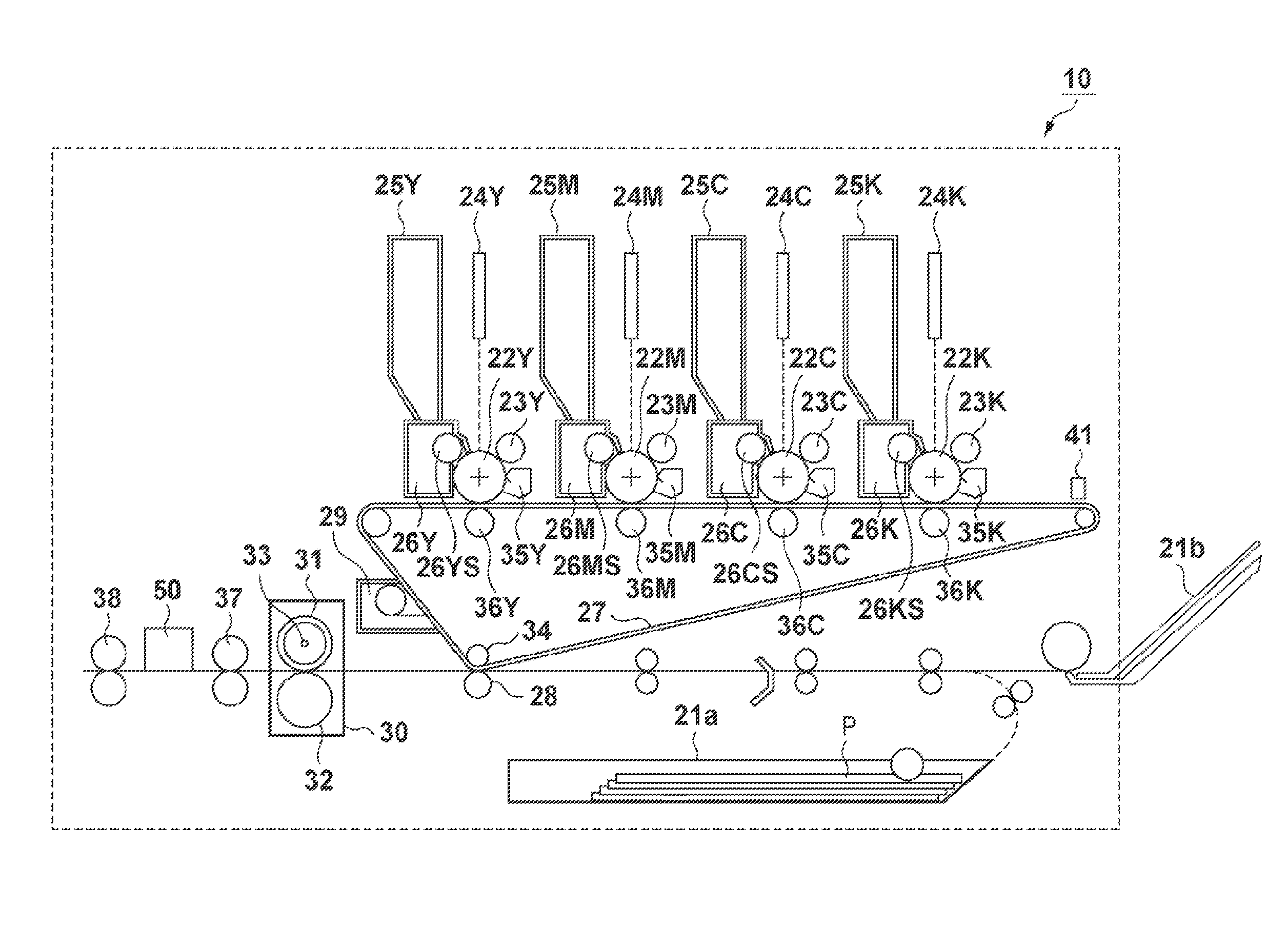
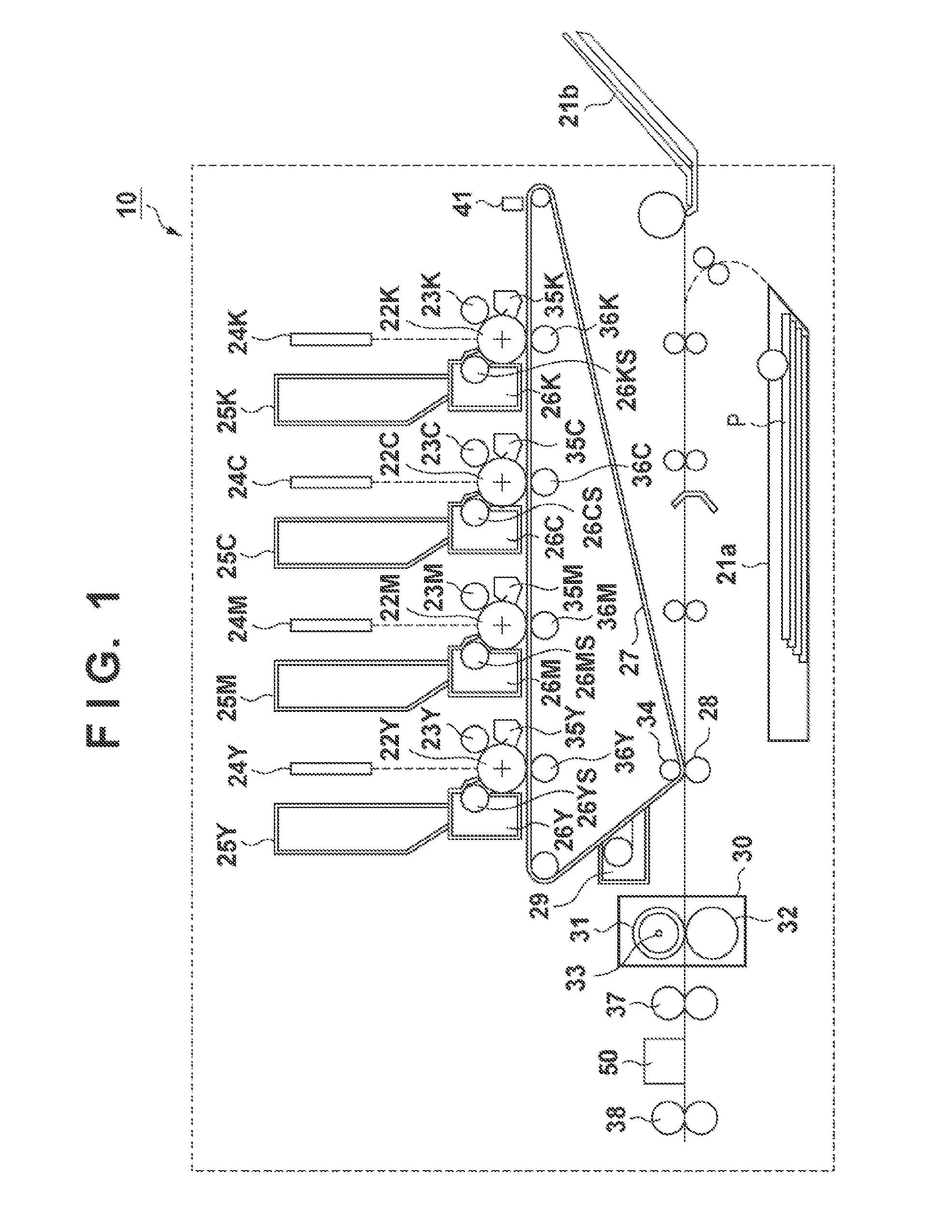
[0035]The arrangement of an image forming apparatus 10 will be described first with reference to FIG. 1, and the operation of an image forming unit that executes an image forming process will also be described. The image forming apparatus 10 includes a plurality of image forming stations corresponding to four developing colors: yellow (Y), magenta (M), cyan (C), and black (K), respectively. The image forming stations include photosensitive drums (image carriers) 22Y, 22M, 22C, and 22K that carry developing material images (toner images) formed using developing materials (toners) of the respective colors, and charging rollers 23Y, 23M, 23C, and 23K that charge the photosensitive drums, respectiv...

second embodiment

[0084]In the above-described first embodiment, a patch image is evaluated at a spatial resolution considering the spatial frequency of color unevenness caused by a specific process included in the image forming process, thereby improving the detection accuracy of color unevenness caused by the specific process. In the second embodiment to be described below, the image forming condition concerning the specific process is adjusted based on the evaluation result in the image forming apparatus according to the first embodiment, thereby reducing color unevenness caused by the process and reducing degradation of image quality. Note that a description of parts common to the first embodiment will be omitted for the sake of simplicity.

[0085]A procedure of adjusting an image forming condition in an image forming apparatus 10 according to this embodiment will be described below with reference to the flowchart of FIG. 9. A case will particularly be explained below in which color unevenness caus...


PUM


Abstract

The present invention provides a mechanism that more appropriately evaluates an image defect caused by a specific process in an image forming apparatus. An image forming apparatus of this invention performs colorimetry of a patch image at a spatial resolution corresponding to the spatial frequency of color unevenness caused by a specific process included in an image forming process. A statistic value based on the n-th (n is an integer of 2 or more) order central moment of a specific color component of a colorimetric value obtained by performing colorimetry at the spatial resolution is compared with a reference value, thereby detecting that the color unevenness caused by the specific process has occurred in the patch image.

Description

BACKGROUND OF THE INVENTION[0001]1. Field of the Invention[0002]The present invention relates to an image forming apparatus, an image processing apparatus, an image processing method, and a recording medium.[0003]2. Description of the Related Art[0004]An electrophotographic color image forming apparatus such as a copying machine, an MFP, or a printer generally performs color correction processing based on density control using a predetermined test chart (patch images). In the color correction processing, for example, patch images for density detection are formed on a photosensitive member, an intermediate transfer member, or a transfer material carrier that carries the transfer material, and the densities of the patch images are detected using a density detection sensor. In addition, an image forming condition such as a charging bias, a developing bias, or an exposure amount in the image forming process is corrected in accordance with the detected density, thereby performing color c...

Claims


Application Information

Patent Timeline
Patent Type & Authority Applications(United States)
IPC IPC(8): H04N1/60
CPCH04N1/6033
Inventor YOKOYAMA, KENSONODA, AKIHITO
Owner CANON KK
Why Eureka
Try Eureka