
Sound field adjustment device

a sound field and adjustment device technology, applied in the direction of stereophonic systems, stereophonic arrangments, electrical appliances, etc., can solve the problem of difficulty in appropriately adjusting the sound pressure, and achieve the effect of improving the sound pressure balance and reducing the deterioration of the sound pressure balan

Inactive Publication Date: 2012-06-21
PIONEER CORP
View PDF2 Cites 18 Cited by
  • Summary
  • Abstract
  • Description
  • Claims
  • Application Information

AI Technical Summary

Benefits of technology

[0008]The above is one example of problems to be solved by the present invention. It is an object of the present invention to provide a sound field adjusting device capable of improving the sound pressure balance at the listening position subjected to the adjustment and diminishing the deterioration of the sound pressure balance at other positions.

Problems solved by technology

Namely, since it is quite difficult to appropriately adjust a sound pressure characteristic of a sound reproduced by plural speakers even if a listener manipulates an audio system to create an appropriate acoustic space by himself, it is required that the audio system side automatically adjusts the sound field.

Method used


Image

  • Sound field adjustment device
  • Sound field adjustment device
  • Sound field adjustment device

Examples


embodiment

[0047]Preferred embodiments of the present invention will be described below with reference to the attached drawings.

1st embodiment

[0048][Speaker Layout]

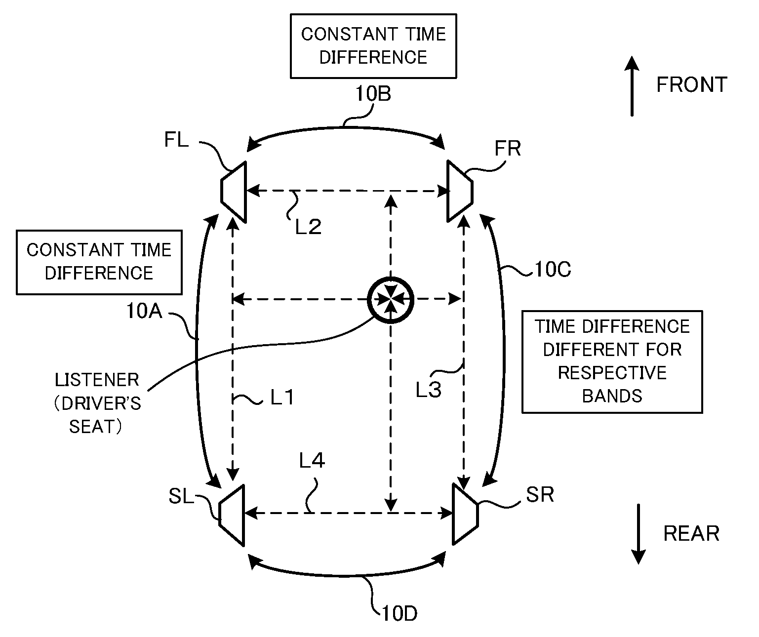
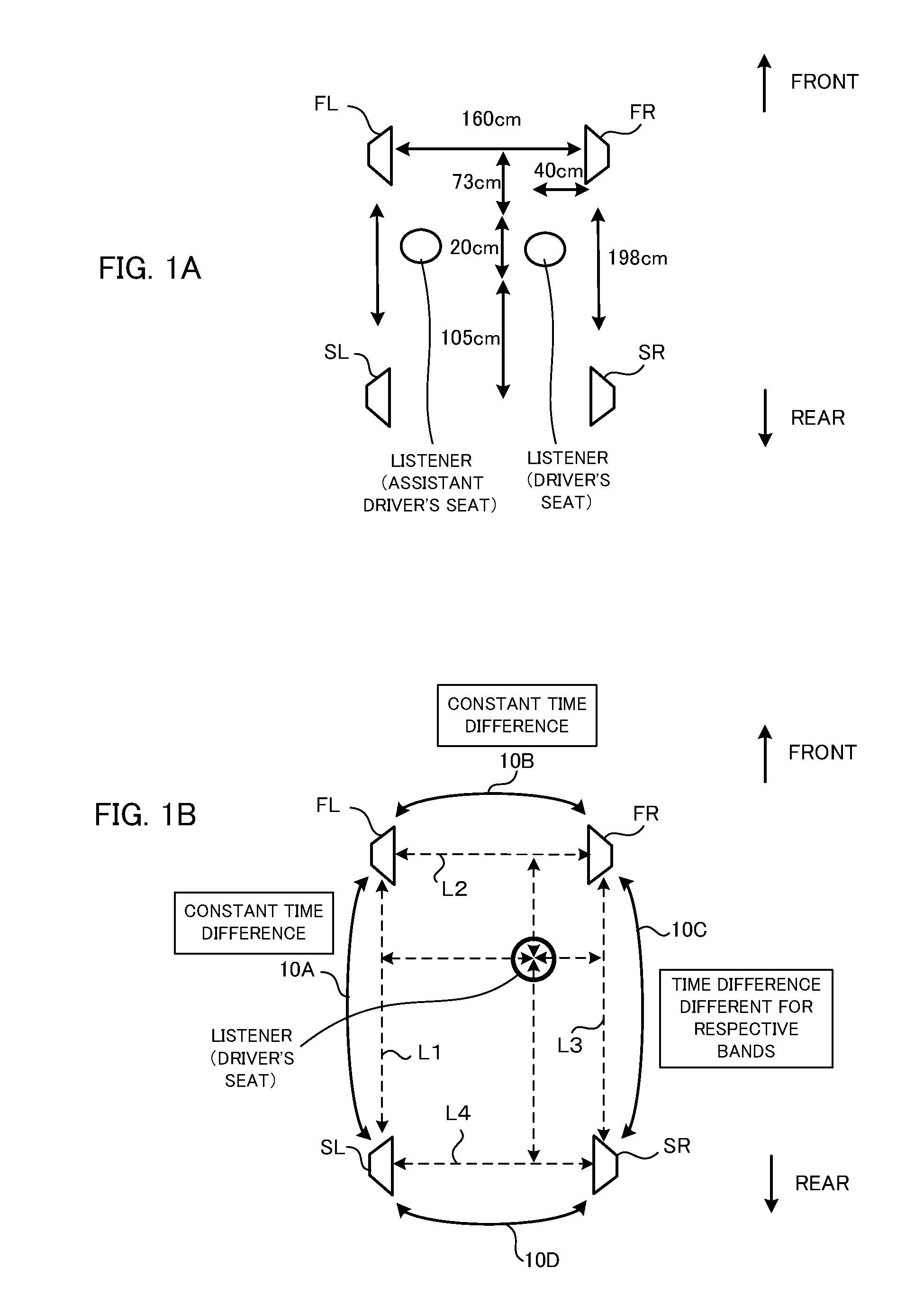
[0049]FIG. 1A shows a speaker layout according to a sound field adjusting device of the first embodiment. FIG. 1A schematically shows speakers and listening positions (listeners) in a vehicle compartment. On the front side of the vehicle compartment, a speaker FR is arranged on the right side and a speaker FL is arranged on the left side. On the rear side of the vehicle compartment, a speaker SR is arranged on the right side and a speaker SL is arranged on the left side. The driver's seat is near the right speakers and the assistant driver's seat is near the left speakers. The positional relationship between those four speakers, the driver's seat and the assistant driver's seat is as indicated by the numerical values in FIG. 1A.

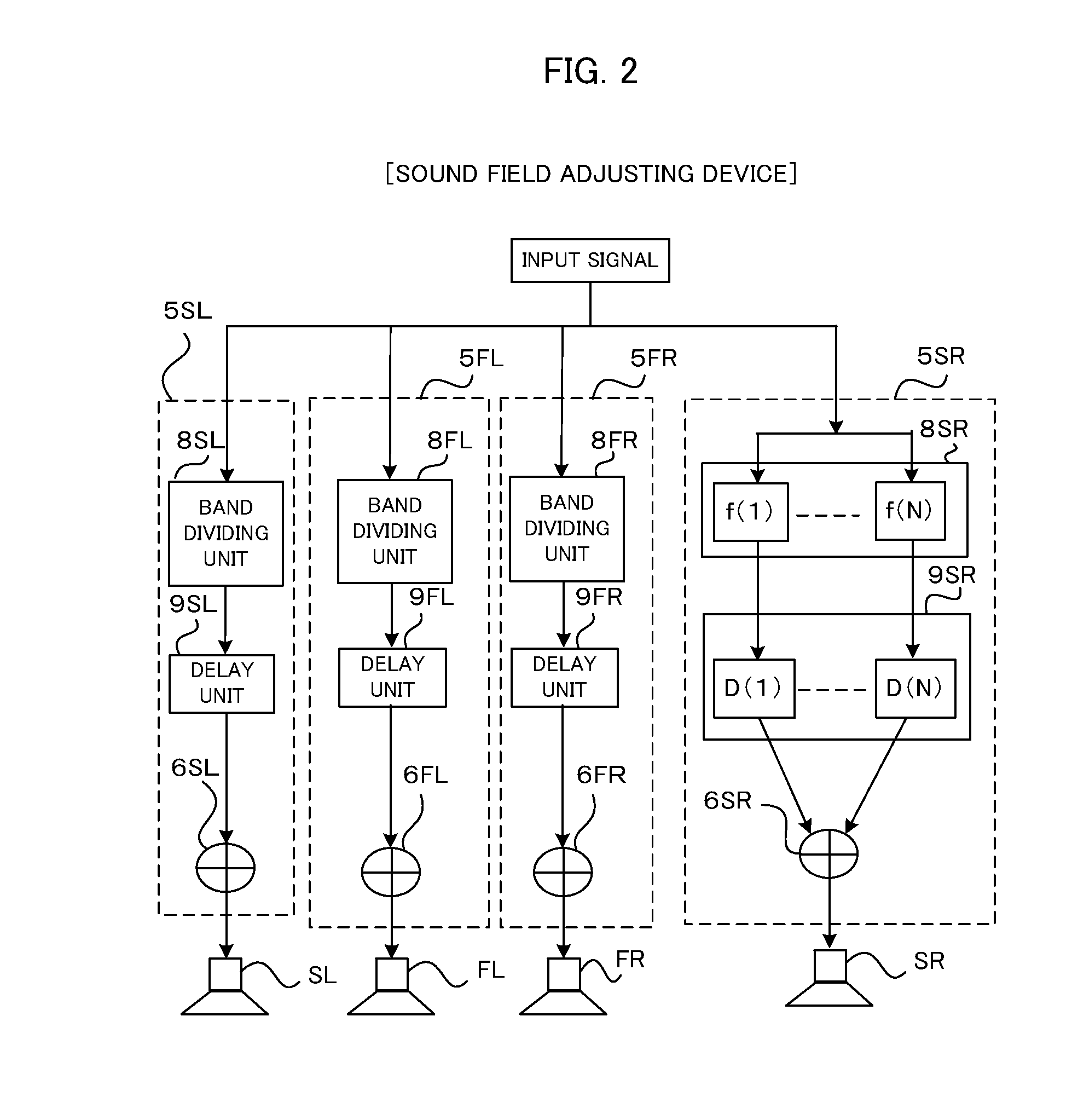
[0050]The outline of the sound field adjusting device will be described with reference to FIG. 1B. The sound field adjusting device includes delay units (not shown) which add a delay amount to the signal outputted from each of the above ...

2nd embodiment

[0098]Next, the second embodiment of the present invention will be described.

[0099][Speaker Layout]

[0100]FIG. 12A shows a speaker layout of the sound field adjusting device according to the second embodiment. FIG. 12A schematically shows the speakers and the listening position (listener position) in the vehicle compartment. The configuration of the speakers is the same as that of the first embodiment shown in FIG. 1. However, the second embodiment supposes a smaller vehicle than that of the first embodiment, and the distances between the speakers and the listening position are shorter. Particularly, in comparison with the first embodiment, the distance between the rear speaker pair 10D and the listening position is near. The positional relationship between four speakers and the driver's seat is as indicated by the numerical values shown in FIG. 12A.

[0101]By using FIG. 12B, the outline of the sound field adjusting device according to the second embodiment will be described. The sound...


PUM


Abstract

A sound field adjusting device reproduces signals from plural speaker pairs arranged in an acoustic space. The device supplies signals to the plural speakers, gives different delays for the respective frequency bands to the signals supplied to at least to a proximity speaker pair which is a speaker pair closest to a listening position among the plural speakers, and gives a delay of a constant delay amount regardless of the frequency band to the speaker pairs other than the speaker pair to which the delays of different delay amounts for the respective frequency bands are given. In this case, the sound field adjusting device does not perform level adjustment, and the sound field adjustment is performed by only adjusting the delay amounts. Therefore, deterioration of sound pressure balance at the position other than the listening position can be avoided, and sound pressure balance at the listening position improved.

Description

TECHNICAL FIELD[0001]The present invention relates to a device for adjusting a sound field.BACKGROUND TECHNIQUE[0002]In an audio system having a plurality of speakers and providing a high-quality acoustic space, it is required to automatically create an appropriate acoustic space providing a presence. Namely, since it is quite difficult to appropriately adjust a sound pressure characteristic of a sound reproduced by plural speakers even if a listener manipulates an audio system to create an appropriate acoustic space by himself, it is required that the audio system side automatically adjusts the sound field.[0003]For example, in a vehicle compartment, the arrangement of the speakers viewed from a listener is not a concentric arrangement of speakers SP1 to SP5 around the listener positioned at the center as shown in FIG. 26A, but is an asymmetric arrangement as shown in FIG. 26B. Therefore, the sound pressure balance is deteriorated at the listener position shown in FIG. 26B.[0004]In...

Claims


Application Information

Patent Timeline
Patent Type & Authority Applications(United States)
IPC IPC(8): H04R5/00
CPCH04S3/002
Inventor OBATA, KENSAKUISEKI, AKIHIROOHTA, YOSHIKI
Owner PIONEER CORP
Learn More