Directional Anti-aliasing filter

a filter and anti-aliasing technology, applied in the field of video/image processing, can solve the problems of over-blurring of video/image, ineffective filtering methods,

Active Publication Date: 2012-06-21
STMICROELECTRONICS ASIA PACIFIC PTE
View PDF8 Cites 7 Cited by
  • Summary
  • Abstract
  • Description
  • Claims
  • Application Information

AI Technical Summary

Benefits of technology

[0005]According to an embodiment of the invention, a directional anti-aliasing filter circuit comprises an input node and an output node, a directional anti-aliasing filter having an input coupled to the input node, an adaptive gain control having an input coupled to an output of the directional anti-aliasing filter, a summer having a first input coupled to an output of the adaptive gain control, a second input coup

Problems solved by technology

Conventional filtering methods are either ineffective in case

Method used


Image

  • Directional Anti-aliasing filter
  • Directional Anti-aliasing filter
  • Directional Anti-aliasing filter

Examples


Embodiment Construction

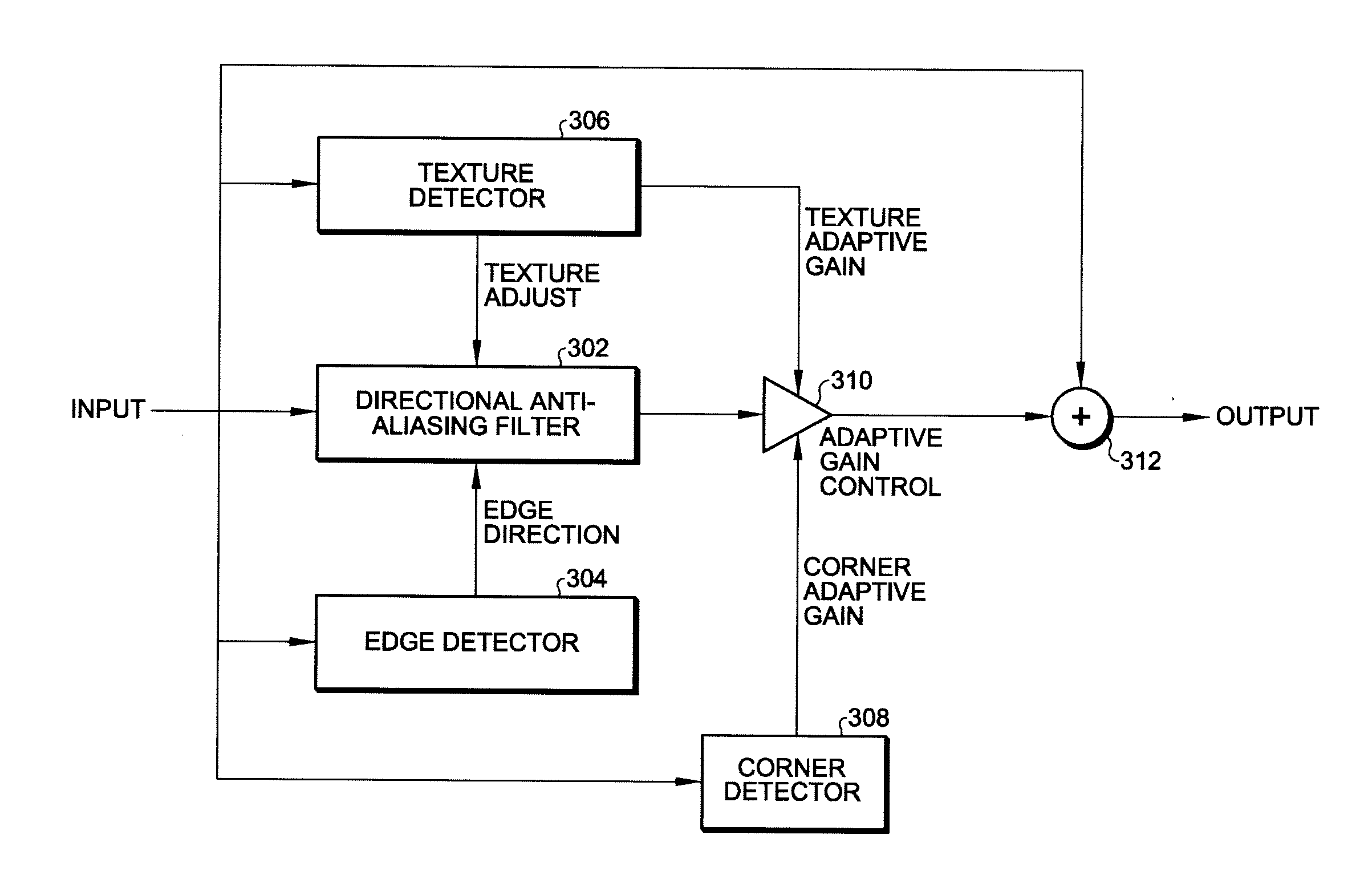
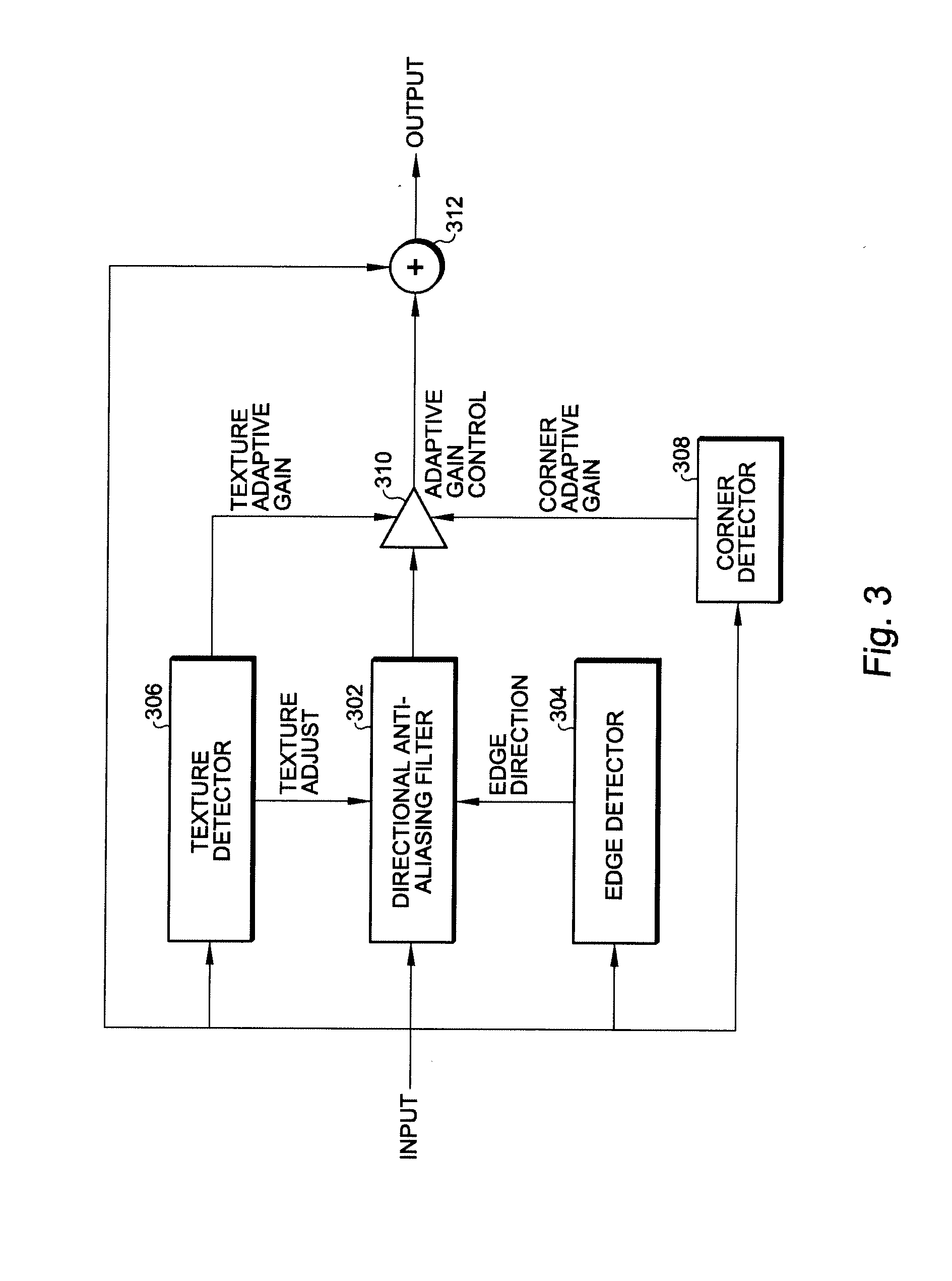
[0028]Referring now to FIG. 3, a directional anti-aliasing filter circuit is shown according to the present invention comprising an input node and an output node, a directional anti-aliasing filter 302 having an input coupled to the input node, an adaptive gain control 310 having an input coupled to an output of the directional anti-aliasing filter 302, a summer 312 having a first input coupled to an output of the adaptive gain control 310, a second input coupled to the input node, and an output coupled to the output node, a texture detector 306 for providing a texture adjust signal to the directional anti-aliasing filter 302 and a texture adaptive gain signal to the adaptive gain control 310, an edge detector 304 for providing an edge direction signal to the directional anti-aliasing filter 302, and a corner detector 308 for providing a corner adaptive gain signal to the adaptive gain control.

[0029]Referring now to FIG. 4, a first alternative embodiment of a directional anti-aliasi...


PUM


Abstract

A directional anti-aliasing filter circuit includes an input node and an output node, a directional anti-aliasing filter having an input coupled to the input node, an adaptive gain control having an input coupled to an output of the directional anti-aliasing filter, a summer having a first input coupled to an output of the adaptive gain control, a second input coupled to the input node, and an output coupled to the output node, a texture detector for providing a texture adjust signal to the directional anti-aliasing filter and a texture adaptive gain signal to the adaptive gain control, an edge detector for providing an edge direction signal to the directional anti-aliasing filter, and a corner detector for providing a corner adaptive gain signal to the adaptive gain control.

Description

BACKGROUND OF THE INVENTION[0001]The present invention relates generally to the field of video / image processing, and in particular video / images quality improvement by removing aliasing artifacts (“jaggies”). The present invention is targeted to television (TV) and set-top box (STB) products and applications.[0002]Aliasing artifacts are typically created by sampling, upscaling / downscaling, or sharpening. Discontinuity or jaggy artifacts can also be introduced by block-based video / image compression methods. Conventional filtering methods are either ineffective in case of strong artifacts or cause over-blurring of the video / image.[0003]A first conventional filtering circuit is shown in FIG. 1. A two-dimensional anti-aliasing filter 102 is used to filter the input signal and to provide a filtered output signal. A second conventional filtering circuit is shown in FIG. 2. A directional anti-aliasing filter 202 is used in conjunction with an edge detector 204 and a summer 206. The directio...

Claims


Application Information

Patent Timeline
IPC IPC(8): G06K9/40
CPCG06T5/002H04N5/14G06T2207/20192G06T2200/12
Inventor HUANG, YONGHUI, LUCAS
Owner STMICROELECTRONICS ASIA PACIFIC PTE
Why Eureka
Try Eureka