Integrated cytometric sensor system and method

Inactive Publication Date: 2012-06-21
RADISENS DIAGNOSTICS
View PDF1 Cites 39 Cited by
  • Summary
  • Abstract
  • Description
  • Claims
  • Application Information

AI Technical Summary

Benefits of technology

[0029]In one embodiment at least one or more of said photodiode pixels are voltage biased in one or more of the following modes: normal, avalanche or Geiger modes, for wide dynamic sensor range operation. By altering the reverse bias voltage, thus putting each photodiode into one of normal, avalanche or Geiger mode, the dynamic range of incident scattering and fluorescent power to which the filter cell array is sensitive to is greatly

Problems solved by technology

Incumbent PMT arrangements require numerous dichroic mirrors and filters to split the wanted wavelengths for detection by separate PMT's, resulting in long and inefficient o

Method used


Image

  • Integrated cytometric sensor system and method
  • Integrated cytometric sensor system and method
  • Integrated cytometric sensor system and method

Examples


Example

DETAILED DESCRIPTION OF THE DRAWINGS

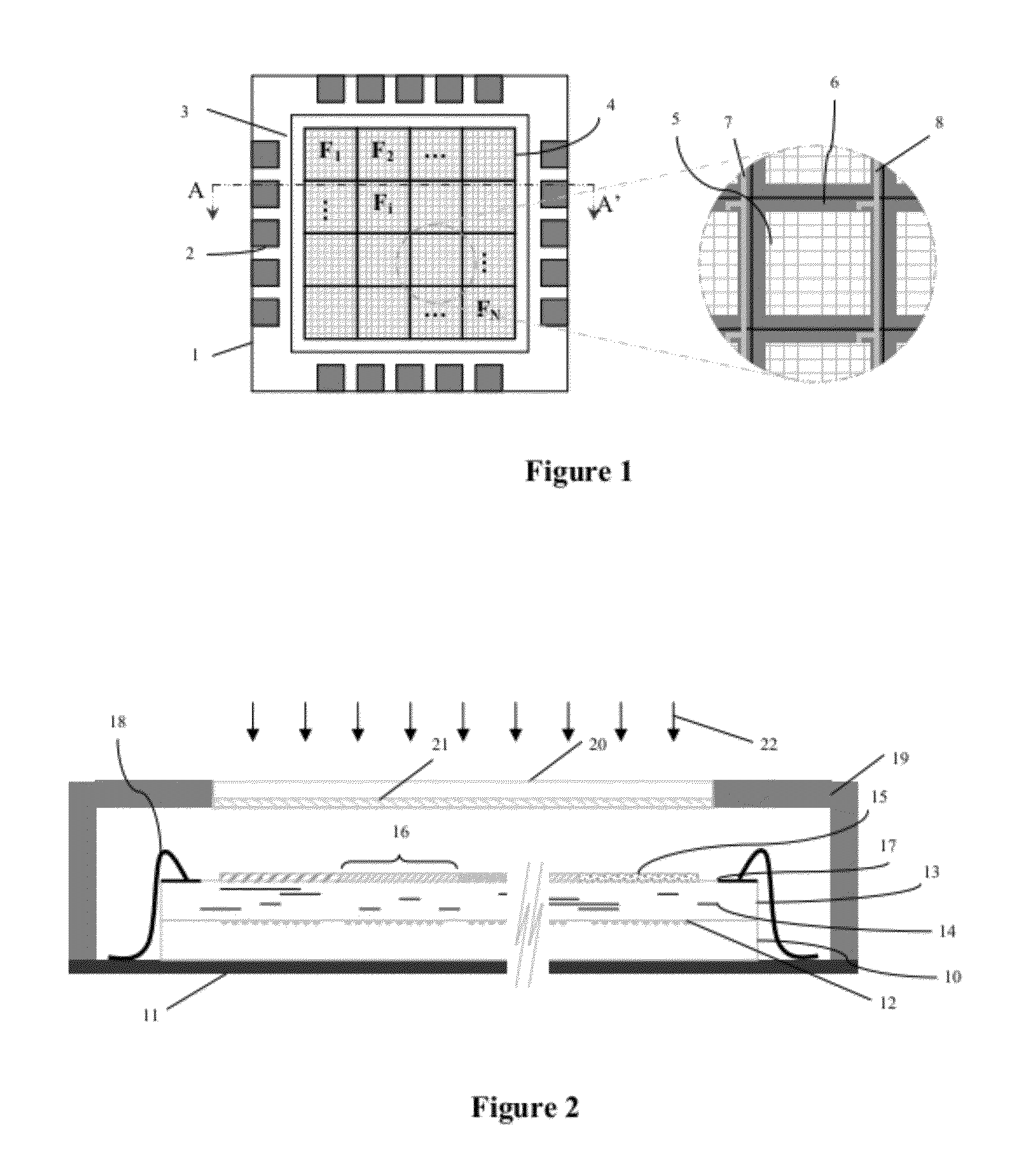
[0081]FIG. 1 illustrates a sensor design of a semiconductor die 1 with IO pads 2 surrounding a core area 3. This core comprises an X*Y array 4 of N filter cells each denoted Fi where i=1 . . . N≦X*Y. Each filter cell has a defined filter characteristic and a photodetector design comprising a plurality of photodiode pixels 5 and areas for other non photo-sensitive circuitry 6, necessary for inter-connection and sampling circuits. In one embodiment the photodiodes may be biased in photon counting, normal, avalanche or Geiger mode of operation. In this arrangement each filter cell column is biased into one of these three modes by connecting biasing voltage rails 7, 8 to each filter cell in the array column. For example, by connecting a voltage greater than the reverse breakdown of the photodiode e.g. −35 V, assuming a −30 V breakdown, to the biasing rail marked 8, the filter cell in the centre of the illustration, and those above and below it, is bia...


PUM


Abstract

The invention provides a flow cytometric system comprising a first sensor positioned axially to a light source; a channel comprising means for receiving a sample target and interposed between said first sensor and light source; and a second sensor placed at an angle to said first sensor adapted to sense side scattering and/or fluorescent components and said first sensor is adapted to sense a forward scattering component in response to light illuminating the sample target in said channel. In another embodiment the invention provides for a wide dynamic range sensor comprising a plurality of photodiode pixels; wherein at least one or more of said photodiode pixels are voltage biased in one or more of the following modes: photon counting, normal, linear avalanche or Geiger modes, for wide dynamic sensor range operation. By altering the reverse bias voltage, thus putting each photodiode into one of normal, avalanche or Geiger mode, the dynamic range of incident scattering and fluorescent power to which the filter cell array is sensitive to is greatly increased, thus increasing the operational sensitivity and specificity of the cytometric instrument.

Description

FIELD OF THE INVENTION[0001]This invention relates generally to an integrated cytometric sensor system and method. In particular the invention relates to a highly integrated and low cost electronic optical sensor device, methods and algorithms for enumeration of microscopic cells, particles or molecules distributed in a sample. The invention also relates to a wide dynamic range optical sensor for use in a flow cytometer.BACKGROUND OF THE INVENTION[0002]Flow cytometry is a powerful method of analysis to determine the cellular / biological content of various types of samples, and in particular samples that contain living cells. In clinical applications, flow cytometers are useful for myriad of applications including lymphocyte counting and classification, for immunological characterization of leukaemias and lymphomas, and for cross-matching tissues for transplants.[0003]In most flow cytometry techniques, cells in a fluid solution are caused to flow individually through a light beam, usu...

Claims


Application Information

Patent Timeline
IPC IPC(8): C12M1/34G01N21/17
CPCG01J3/2803G01J3/36G01J3/44G01J2003/1213G02B5/288G01N15/1436G01N21/6428G01N2021/6482G02B5/201G01N15/1434G01N15/1459
Inventor O'BRIEN, JEREMIAHBARRY, LEE
Owner RADISENS DIAGNOSTICS
Why Eureka
Try Eureka