Dynamic range module, system and method

Inactive Publication Date: 2020-05-28
QUINC TECH INC
View PDF0 Cites 1 Cited by
  • Summary
  • Abstract
  • Description
  • Claims
  • Application Information

AI Technical Summary

Benefits of technology

[0018]Aspects of the present disclosure relate to a dynamic range module, system and method in general. Aspects of the present disclosure also apply to dynamic range module, system and method implemented into devices benefiting from dy

Problems solved by technology

Another generalized situation is where a platform's own electronic emitters transmit extremely strong signals that disrupt the operation of the platform's other operational equipment.
For example, in radios, the ability to transmit and receive data at the same time and on the same frequency is limited in part by the dynamic range of the receiver's ADC.
This strong signal can saturate the ADC or cause the automatic gain control circuit to increase the value of the ADC's LSB, which makes it difficult to measure the weaker signals.
This has the advantage of preventing the strong signal from creating distortion, but it has the disadvantage that decreasing the gain means that the system cannot resolve weaker signals.
Unfortunately, interleaving ADCs often cannot provide enough dynamic range without unreasonable complexity and expense.
For example, if an application required a factor of 100 increase in dynamic range, this approach would require the precise interleaving of 100 ADCs, which would be expensive and prone to error.
This can significantly reduce the strength of the radio's transmitted signal at the radio's receiver, but it cannot completely remove the signal.
Furthermore, this method requires additional components and complexity, which scales exponentially with the number of transmitters a

Method used


Image

  • Dynamic range module, system and method
  • Dynamic range module, system and method
  • Dynamic range module, system and method

Examples


Example

[0038]Aspects of the present disclosure relate to a dynamic range module, system and method in general. Aspects of the present disclosure also apply to the dynamic range module, system and method being implemented into devices benefiting from dynamic range such as radios, radar, signals receivers, or test and measurement equipment. The dynamic range module uses one or more superconducting quantum interference devices (SQUIDs) to increase the dynamic range of the system. The disclosure relates to measuring and processing signals, and more particularly to increasing the ratio of a maximum signal to a minimum signal that a system can process.

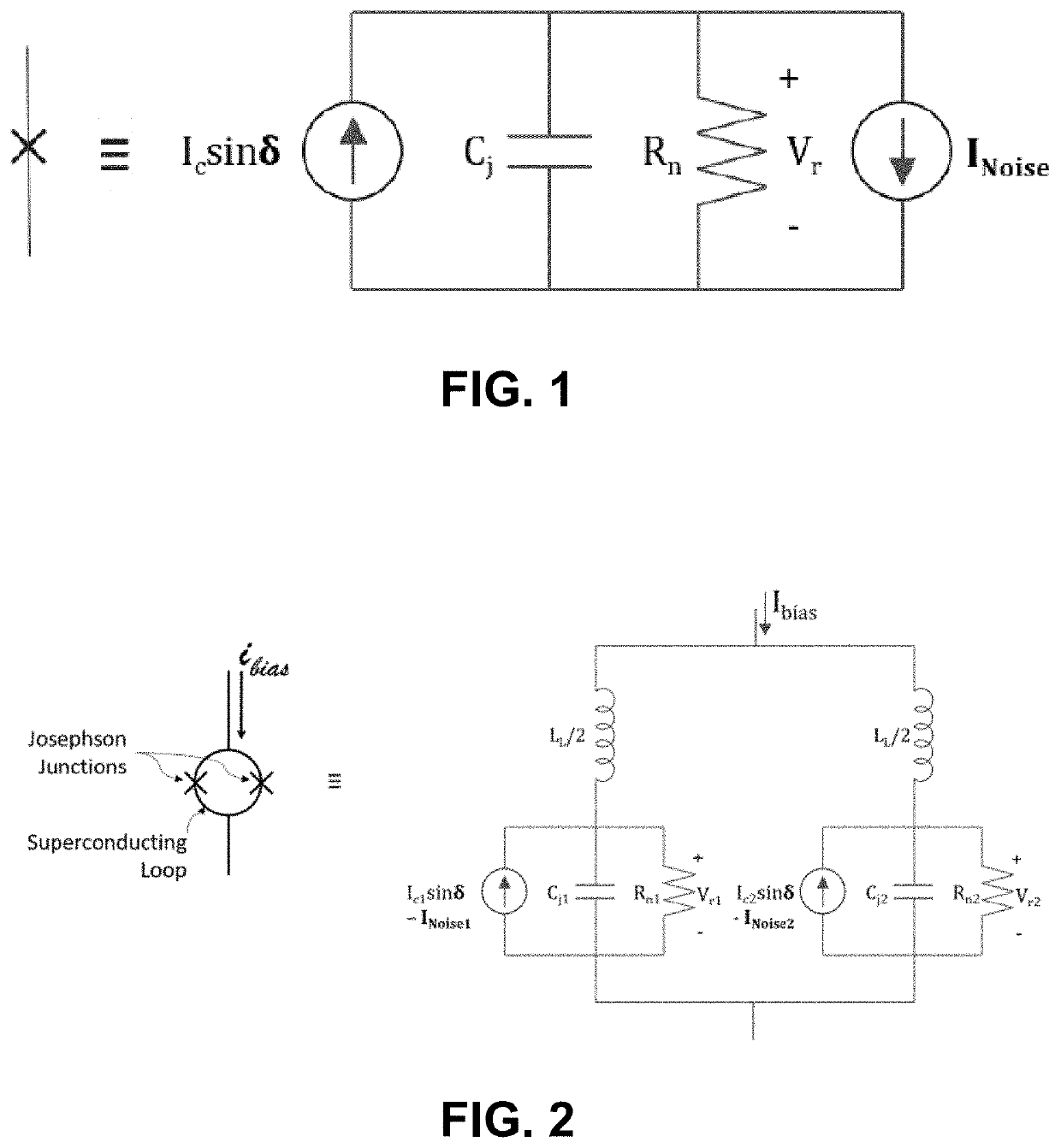
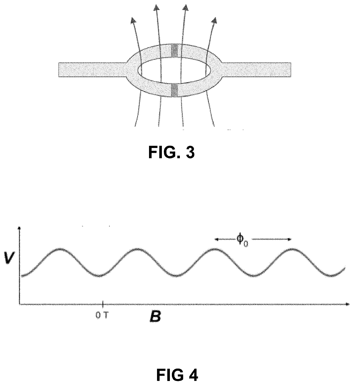
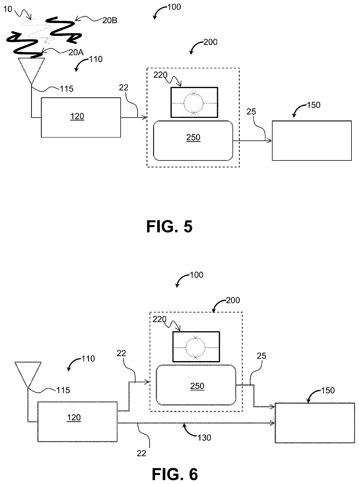
[0039]Any device that produces an output signal that is periodic with respect to an input signal can be used to create the dynamic range module. One example of a device that produces a response that is periodic with respect to its input is a superconducting quantum interference device (SQUID). A SQUID produces a voltage response that is periodic wi...


PUM


Abstract

Aspects of the present disclosure relate to a dynamic range module, system and method in general. Aspects of the present disclosure also apply to dynamic range module, system and method implemented into devices benefiting from dynamic range such as radios, radar, test and measurement equipment, and other signals receivers. The dynamic range module uses one or more superconducting quantum interference devices (SQUIDs) to increase the dynamic range of the system.

Description

CROSS-REFERENCE TO RELATED APPLICATIONS[0001]This application claims priority to U.S. provisional patent application 62 / 740,672, filed Oct. 3, 2018 and entitled DYNAMIC RANGE MODULE, SYSTEM AND METHOD, the contents of which are incorporated herein by reference in its entirety.BACKGROUND OF THE INVENTIONTechnical Field[0002]The present disclosure generally pertains to mechanisms and methods for improving signal detection and amplification, and is more particularly directed towards mechanisms and methods for improving dynamic range in systems.Related Art[0003]The present disclosure is generally intended to address a problem that arises when a system does not have enough dynamic range to detect signals of interest because of the presence of much stronger signals. This situation could occur when a radio is transmitting and receiving using the same bandwidth resource. In that situation, the radio's transmitted signal would be much stronger than received signal and would prevent the radio...

Claims


Application Information

Patent Timeline
IPC IPC(8): G01R33/035H03K3/38
CPCH03K3/38G01R33/0356G01R29/0878G01R29/0892G01R15/20
Inventor LEMAY, LEE
Owner QUINC TECH INC
Why Eureka
Try Eureka