Adaptive ECG wandering correction

Inactive Publication Date: 2012-06-21
ANALOG DEVICES INC
View PDF5 Cites 28 Cited by
  • Summary
  • Abstract
  • Description
  • Claims
  • Application Information

AI Technical Summary

Benefits of technology

[0005]In various embodiments of the present invention, efficient, fast, and accurate filtering of the wandering signal (i.e., wandering noise) from an observed ECG signal is provided so that the ECG signal can be analyzed in real time. This is achieved, in part, by estimating several signal components compr

Problems solved by technology

This decreases noise in the ECG sig

Method used


Image

  • Adaptive ECG wandering correction
  • Adaptive ECG wandering correction
  • Adaptive ECG wandering correction

Examples


Embodiment Construction

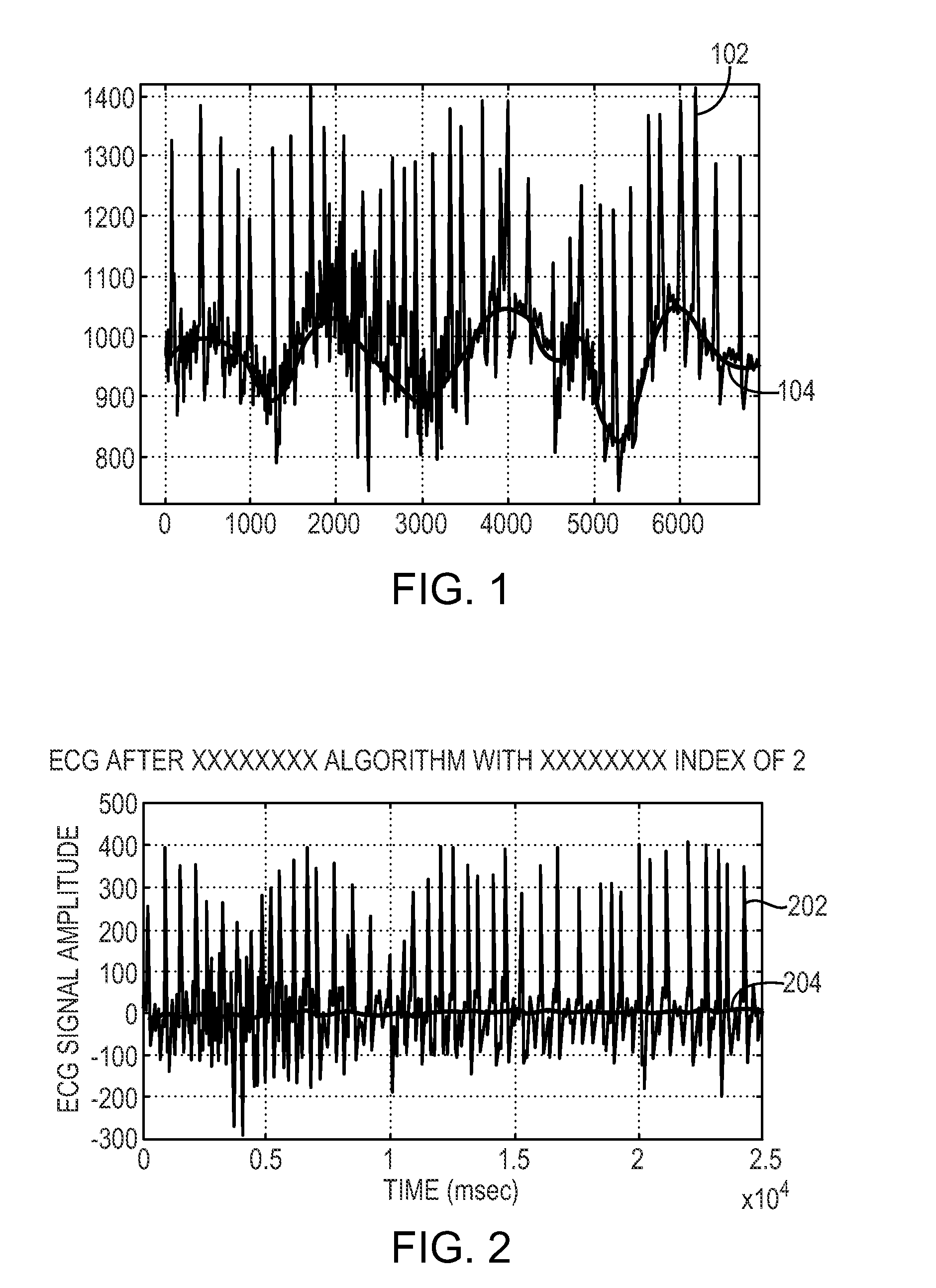
[0029]As shown in FIG. 1, in a typical ECG signal 102 recorded from electrodes attached to a patient, the baseline 104 of the signal 102, i.e., a reference voltage relative to which the voltage of the signal 102 varies in time, is not steady (i.e., substantially constant). The baseline 104 wanders, changing over a certain range over time at a certain frequency, thereby adding wandering noise to the true or desired ECG signal contained in the signal 102. The values of the observed ECG signal 102 relative to the baseline 104 are required in subsequent analysis of the ECG signal 102 for diagnostic or other purposes. These relative values are obtained by removing, i.e., filtering the wandering noise. In the filtered ECG signal 202 shown in FIG. 2, the baseline 204 is substantially flat, and does not vary with time. Therefore, the values of the filtered signal 202 can be used directly in diagnosis and treatment of a patient. It should be understood that although various embodiments of th...


PUM


Abstract

A received signal is filtered by filtering a group of estimated components of the received signal from the received signal such that the noise and/or distortion in the received signal is minimized.

Description

FIELD OF THE INVENTION[0001]The invention relates generally to noise reduction in signals.BACKGROUND[0002]Surface electrocardiograms (ECGs) have long been central to the diagnosis, management and prognosis of patients with coronary disorders. In most cases, clinical care focuses on physician examination of an ECG and any arrhythmias detected through continuous monitoring.[0003]To obtain ECG waveforms, electrodes are connected to a patient for detecting the ECG signal. Sometimes the signal is provided to a recording device worn by the patient. The sensed signal data are analyzed, periodically or in real-time, for diagnostic purposes. Frequently, the analysis of the ECG signal data becomes erroneous because the baseline of the observed ECG waveform varies considerably. Such variations are known as baseline wander, and can be caused by, e.g., respiration, poor electrode contact and sweating. There are both high and low amplitude wanders across a range of frequencies. Because the spectr...

Claims


Application Information

Patent Timeline
IPC IPC(8): A61B5/0408
CPCA61B5/04014A61B5/0402A61B5/04017A61B5/316A61B5/318A61B5/7203A61B5/347
Inventor STEIN, YOSEFSAPIR, YANIV
Owner ANALOG DEVICES INC
Why Eureka
Try Eureka