Mounting/dismounting jig for combustor tail pipe and tail pipe installation method

Active Publication Date: 2012-06-28
MITSUBISHI POWER LTD
View PDF1 Cites 28 Cited by
  • Summary
  • Abstract
  • Description
  • Claims
  • Application Information

AI Technical Summary

Benefits of technology

[0034]According to the tail cylinder attaching and detaching fixture of the invention, it is possible to attach and detach the tail cylinder to and from the inside of the casing even in a restricted space with a simple structure.
[0035]Fu

Problems solved by technology

Furthermore, it is difficult to ensure a foothold above an installatio

Method used


Image

  • Mounting/dismounting jig for combustor tail pipe and tail pipe installation method
  • Mounting/dismounting jig for combustor tail pipe and tail pipe installation method
  • Mounting/dismounting jig for combustor tail pipe and tail pipe installation method

Examples


first embodiment

[0068]Hereinafter, a first embodiment according to the invention will be described by referring to the drawings.

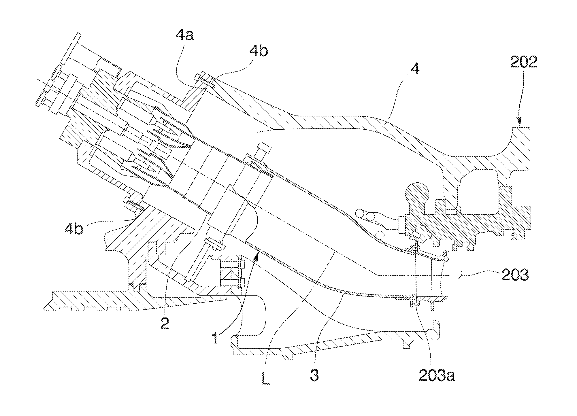
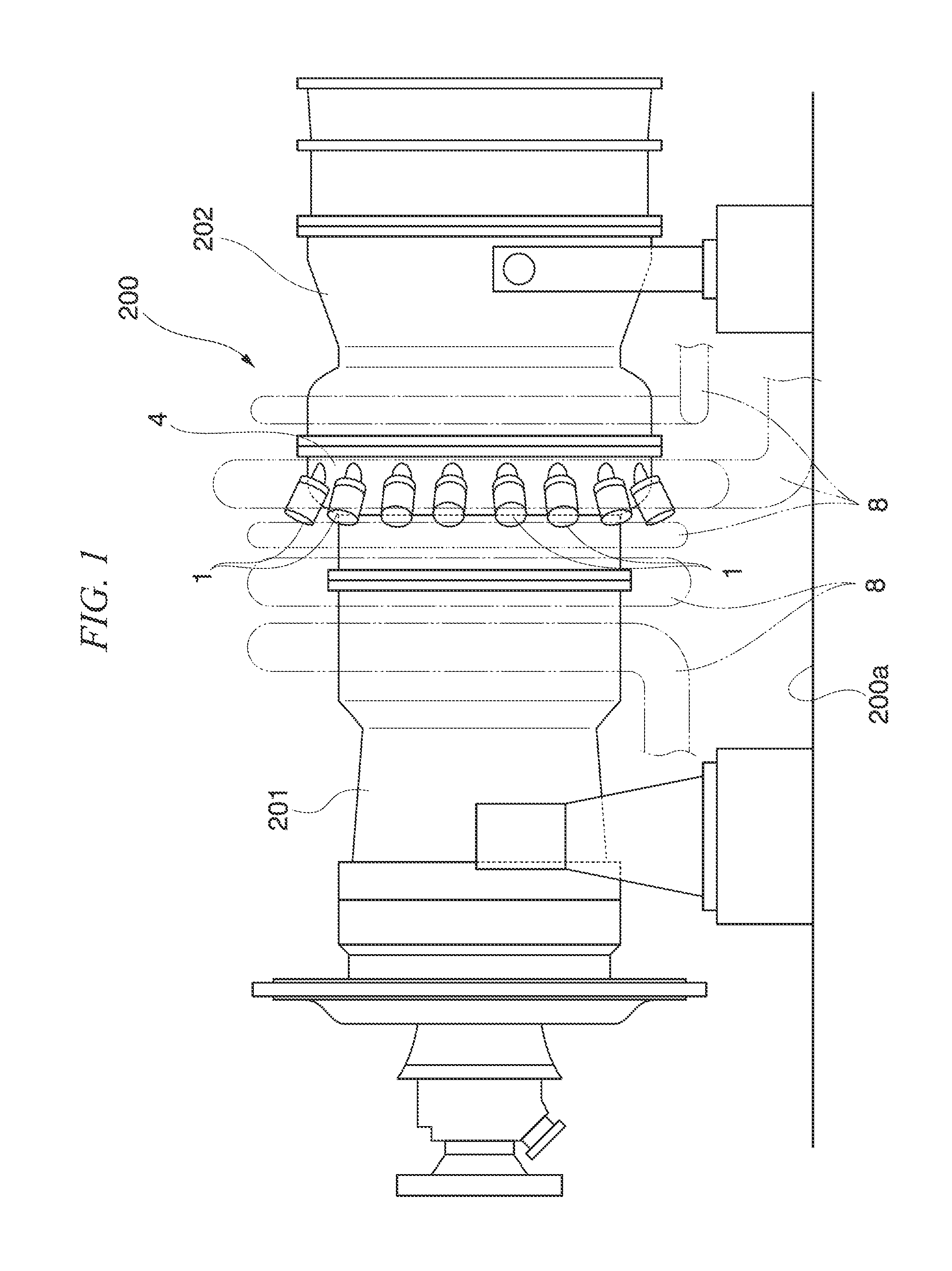
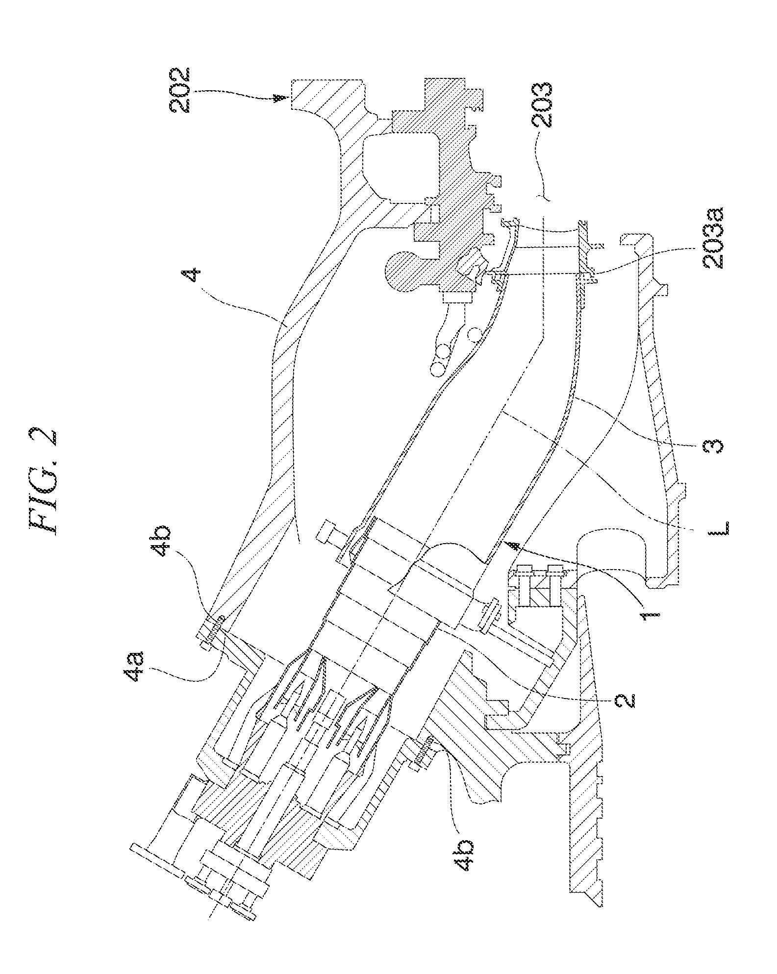
[0069]Furthermore, in a gas turbine 200, a combustor 1 and the attachment structure of the combustor 1 and a casing 4 are basically the same as those of the related art. For this reason, only differing features will be described.

[0070]FIG. 4 shows a state where an attaching and detaching fixture 10 of a tail cylinder 3 of the embodiment is attached to a casing 4. As shown in FIG. 4, the attaching and detaching fixture 10 includes a guide portion 11 that is disposed along the direction of the axis line L of the combustor 1, a moving portion 12 that is attachable to and detachable from the tail cylinder 3 and is movable along the guide portion 11, and an advancing and retracting mechanism 13 that advances and retracts the tail cylinder 3 attached to the guide portion 11 through the moving portion 12 along the direction of the axis line L of the combustor 1.

[0071]As shown in ...

second embodiment

[0114]Next, a second embodiment of the invention will be described. FIG. 32 shows the second embodiment of the invention. Furthermore, in this embodiment, the same reference numerals are given to the same components used in the above-described embodiment, and the description thereof is omitted here.

[0115]As shown in FIG. 32, an attaching and detaching fixture 110 does not include the second casing attaching plate 26, the support member 27, the fixing plate 28, and the base end member 21, but a guide portion 111 guiding the tail cylinder 3 so as to be movable along the axis line L of the combustor 1 is only the front end member 20. That is, in the guide portion 111, a front end 111a is supported by the inner surface of the casing 4 in a manner such that the support pin 22 provided in the front end 111a is fitted to the concave portion 4c of the casing 4. Further, the base end 111b is supported by the outer surface of the casing 4 by using the first casing attaching plate 23 as the ba...


PUM


Abstract

Provided is a tail cylinder attaching and detaching fixture that attaches and detaches a tail cylinder to and from a casing, the tail cylinder being included in a combustor inserted into the casing so that the front end is connected to an inlet portion of a combustion gas passageway, the tail cylinder attaching and detaching fixture including: a guide portion of which the front end is disposed inside the casing and the front end and the base end are respectively supported by the casing and which supports the tail cylinder so as to be movable in the axial direction of the combustor; and an advancing and retracting mechanism that advances and retracts the tail cylinder in the axial direction.

Description

TECHNICAL FIELD[0001]The present invention relates to a tail cylinder attaching and detaching fixture that attaches and detaches a tail cylinder of a combustor to and from a casing of a gas turbine and a tail cylinder attaching method.[0002]Priority is claimed on Japanese Patent Application No. 2009-214815, filed Sep. 16, 2009, the content of which is incorporated herein by reference.BACKGROUND ART[0003]As shown in FIGS. 1 and 2, a gas turbine 200 generally includes a compressor 201 that produces compressed air, a plurality of combustors 1 that produces a combustion gas by mixing fuel with the compressed air produced in the compressor 201, and a turbine 202 that is driven by the combustion gas produced in the combustor 1. The combustor 1 includes an inner cylinder 2 to which compressed air and fuel are supplied to be burned and a tail cylinder 3 that introduces the combustion gas produced in the inner cylinder 2 into a combustion gas passageway 203 of the turbine 202. The plurality ...

Claims


Application Information

Patent Timeline
IPC IPC(8): F23R3/02
CPCF01D9/023F05D2230/70F05D2230/60F01D25/285F02C7/00F02C7/20F23R3/42F23R3/60F01D25/28
Inventor SHIOTANI, SHIGETOSHIARASE, KENICHIYOSHIDA, NAOHIKOMIZOKAMI, SHUJIHASEGAWA, OSAMUTSUZUKI, SATOSHITAKEDA, HIROHITO
Owner MITSUBISHI POWER LTD
Why Eureka
Try Eureka