Drinking container with suction pipe

a technology of drinking containers and suction pipes, which is applied in the direction of caps, liquid handling, and closures using stoppers, etc., can solve the problems of air pressure in the containers, hot liquids are prone to spouting out of the open end of the straw, and it is not convenient to replace the valve body with this structure, etc., to achieve convenient replacement, easy cleaning, and balanced pressure in the container

Inactive Publication Date: 2012-06-28
CHIANG YAT SAN
View PDF25 Cites 22 Cited by
  • Summary
  • Abstract
  • Description
  • Claims
  • Application Information

AI Technical Summary

Benefits of technology

[0015]For the abovementioned structures utilized, during the slide sheet is being open, the float venting valve is flicked under the action of the elastic protrusions, and high-pressured air in the interior is discharged through the venting passage between the float venting valve and the venting valve hole, and the pressure in the container is balanced. When the slide sheet is completely open or closed, the two protrusions on the slide sheet press tightly against the float venting valve, and the elastic protrusion is forced to cling to the contact surface of the venting valve hole for waterproof sealing. The requirement to the process dimension of assembling is lower, as the float venting valve can be waterproof sealed only by the two protrusions on the...

Problems solved by technology

When hot liquids are contained in these containers with prior structures, air pressure in the containers will be heighten because of heat, which results in that the hot liquids are prone to spouting out of the open end of the straw when it is open.
While th...

Method used


Image

  • Drinking container with suction pipe
  • Drinking container with suction pipe
  • Drinking container with suction pipe

Examples


Embodiment Construction

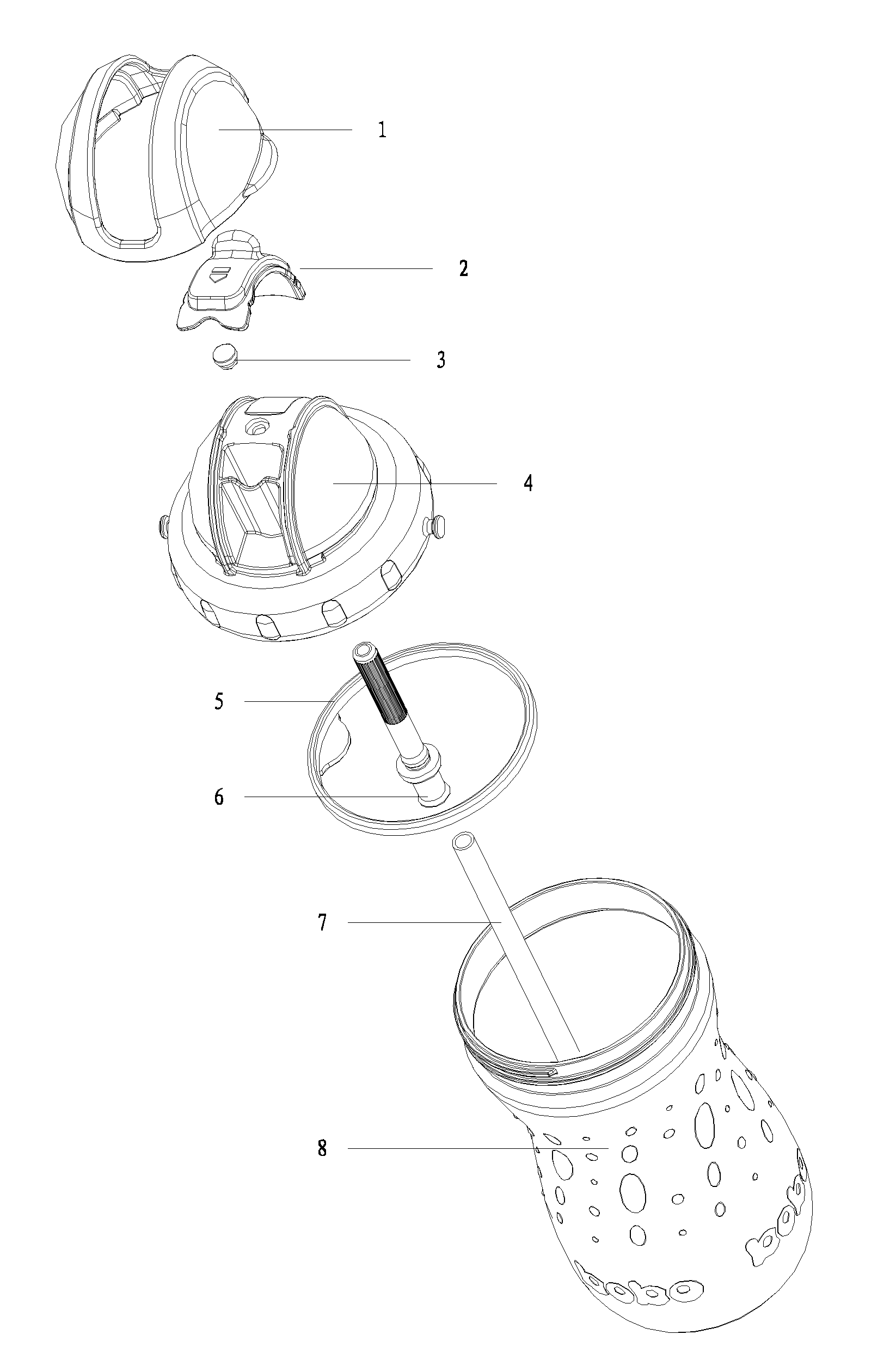
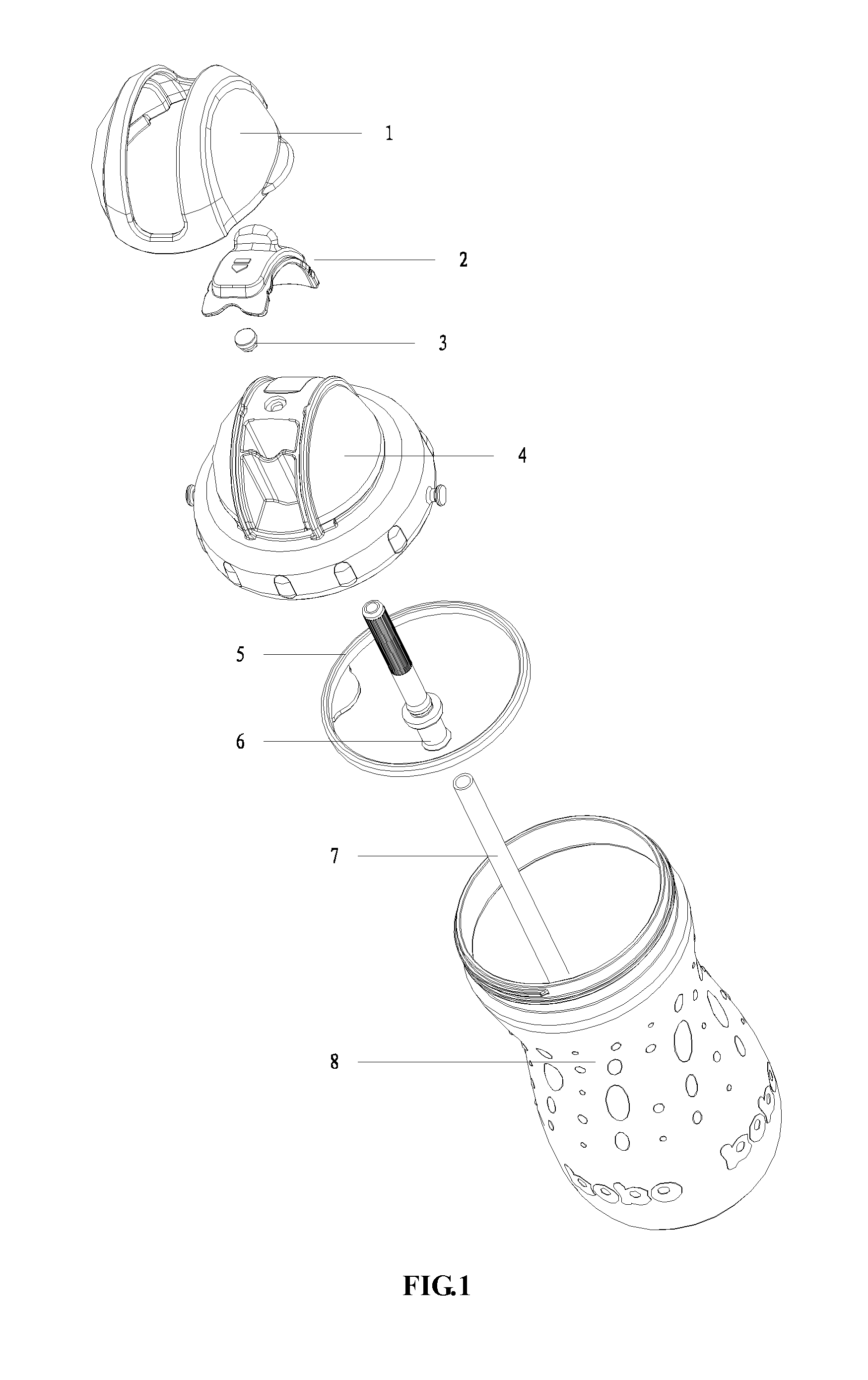
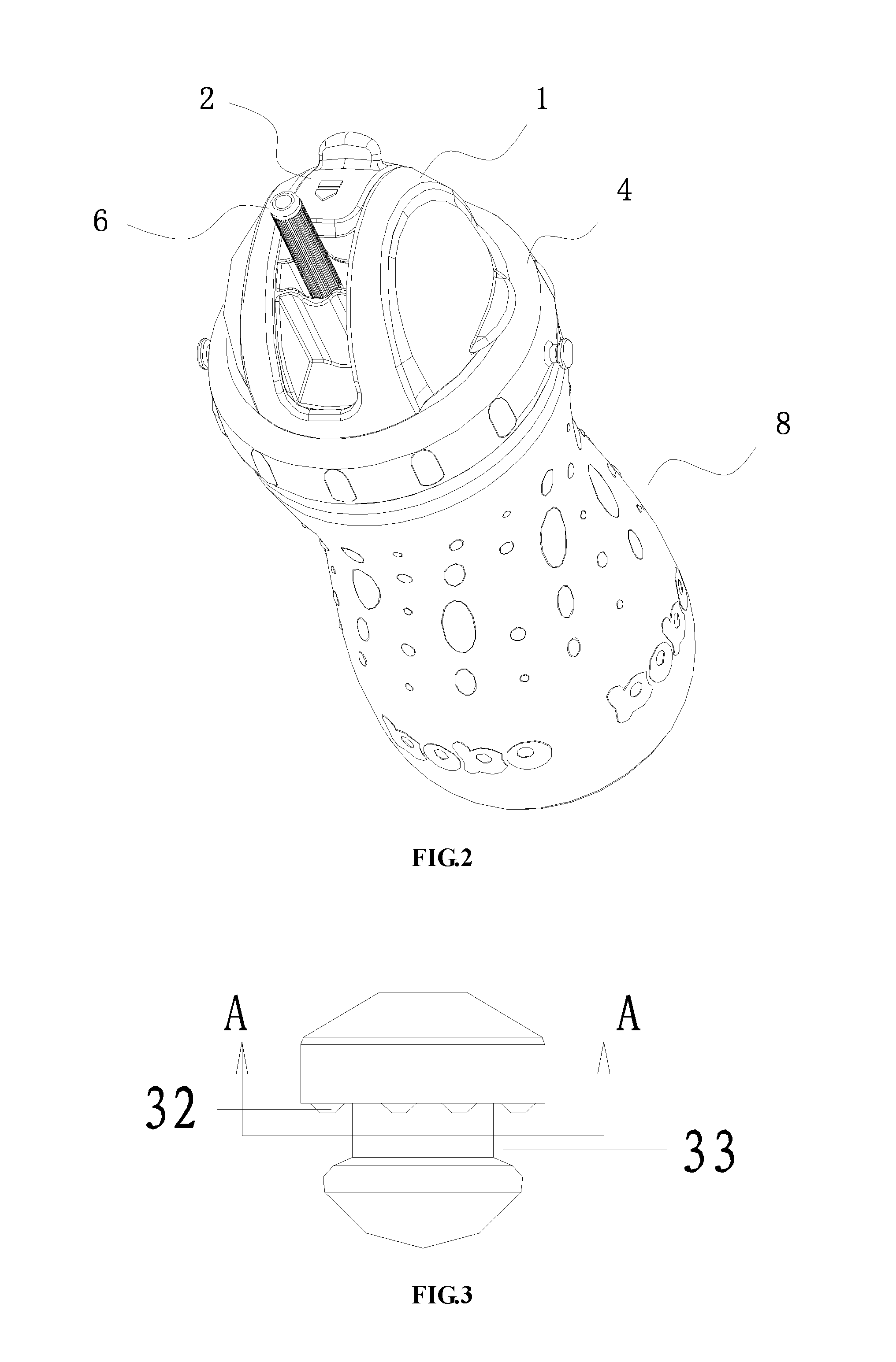
[0029]As seen in FIGS. 1 to 13, a drink container with suction pipe comprises a container body 8, a cap assembly and a flexible straw 6, and the cap assembly comprises a inner cap 4 and a valve assembly which can open and close the passage between inside and outside of the container body 8 by respectively extending and bending the flexible straw 6. The inner cap 4 is mounted on the opening of the container body 8 by waterproof sealing, and the valve assembly comprises a slidable slide sheet 2 which is positioned and mounted on the outer side of the inner cap 4 and a bending fulcrum unit 45 which sustains against the bending portion of the straw 6, and the straw 6 is mounted to a mounting hole 42 for straw of the inner cap 4 by waterproof sealing. The straw 6 is bent from the bending fulcrum unit 45 when the slide sheet 2 slides freely forward to press the bending portion 63 of the straw 6; and the straw 6 returns to upstanding position to communicate to outside when the slide sheet ...


PUM


Abstract

A drink container with suction pipe is provided. The container comprises a container body, a cap assembly and a flexible straw; the cap assembly comprises an inner cap and a valve assembly which can open and close the passage between inside and outside of the container body by respectively extending and bending the flexible straw; and the cap assembly also comprises a venting switch assembly which comprises a venting valve hole mounted on the inner cap, a float venting valve, protrusions mounted respectively on both ends of the inner side of the slide sheet, and hollow portion mounted between two the protrusions. The float venting valve is movably mounted to the venting valve hole and comprises one or a plurality of elastic protrusions on its contact surface. When the slide sheet is in its completely open or closed position, one of the protrusions mounted on both ends of the inner side of the slide sheet is pressed against the float venting valve to press the elastic protrusion of the float venting valve to cling to the surface of the venting valve hole for waterproof sealing. Therefore, the requirement to the process dimension of assembling of the venting switch assembly in accordance with this invention is lower, and the float venting valve is easy to be replaced.

Description

FIELD OF THE INVENTION[0001]The present invention relates to drinking containers with suction pipe, and more particularly to drinking containers which can prevent hot liquids spouting out of the open end of the straw when hot liquids are contained therein.BACKGROUND OF THE INVENTION[0002]Drinking containers for consumption using straws are known. When hot liquids are contained in these containers with prior structures, air pressure in the containers will be heighten because of heat, which results in that the hot liquids are prone to spouting out of the open end of the straw when it is open. In order to solve this problem, it is necessary to mount a ventilating device on inner cap. For example, Chinese patent CN200610165636.7 discloses a cap for drink container and a drink container, wherein a valve with air vent is mounted on the inner cap for ventilating, and two valve cores are mounted on a slide sheet in order that the valve cores will block up the air vent of the valve to seal u...

Claims


Application Information

Patent Timeline
IPC IPC(8): B65D51/16
CPCB65D47/066B65D51/1644B65D47/268
Inventor CHIANG, YAT SAN
Owner CHIANG YAT SAN
Why Eureka
Try Eureka