Device and method for a rotation of the wheels of the landing gear of aircraft

a technology for landing gear and wheels, applied in the field of aircraft, can solve the problems of increasing air pollution, noise source, and manoeuvres on the ground by aircraft, and achieve the effect of avoiding fuel consumption

Inactive Publication Date: 2012-06-28
GAIA MARIO
View PDF20 Cites 12 Cited by
  • Summary
  • Abstract
  • Description
  • Claims
  • Application Information

AI Technical Summary

Benefits of technology

[0008]This invention is on the contrary addressed at actually resolving in an innovative way the technical problem explained beforehand, by making the wheels of the landing gear of aircraft “drive wheels”, both backward and forward, without having to resort either to external help or to the thrust of the motors or the propellers, therefore without useless consumption of fuel and in safety conditions also when near the fingers.

Problems solved by technology

The function of the propulsion system at a low power for the movements on the ground of an aircraft, the movements on the ground being however not very efficient, means an important, costly consumption of fuel, an increase in the level of air pollution and it is the source of noise on approaching the airports.
Therefore, the manoeuvres on the ground by aircraft have always been a problem at least for the considerable limits and disadvantages that they involve.
However, in the first case it would be necessary to re-design and also largely modify the landing gear so as to be able to incorporate the motor and control differential; in the second case the control mechanism is on the outside of the tyre of the wheels in a position and with unacceptable volume.
However this device does not seem to be immediately applicable to the landing gear in that the latter is equipped with a braking system that does not include a brake calliper intended as the one for the aircraft on the ground.

Method used


Image

  • Device and method for a rotation of the wheels of the landing gear of aircraft
  • Device and method for a rotation of the wheels of the landing gear of aircraft
  • Device and method for a rotation of the wheels of the landing gear of aircraft

Examples


Embodiment Construction

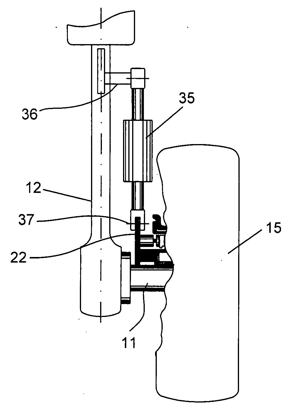
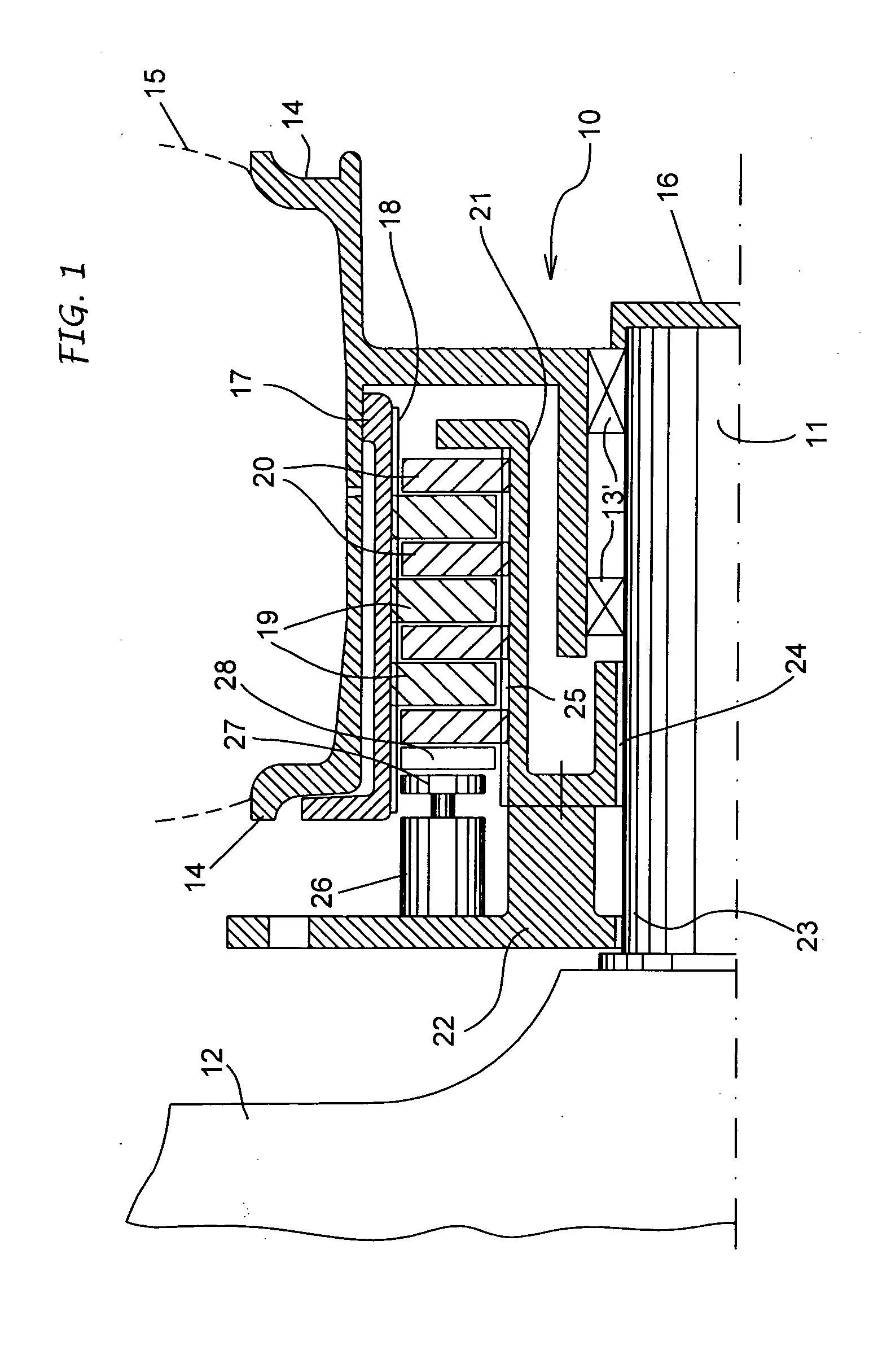
[0027]The wheel-brake-support system of a landing gear 10 schematized in FIG. 1 is the type in use on many aircraft, and is therefore well known and is shown only as an example. Its representation, the same applying to every other one reproduced in the remaining figures, is simplified, different elements having been omitted which are necessary for the correct mechanical realisation, above all to be carried out according to the known technique.

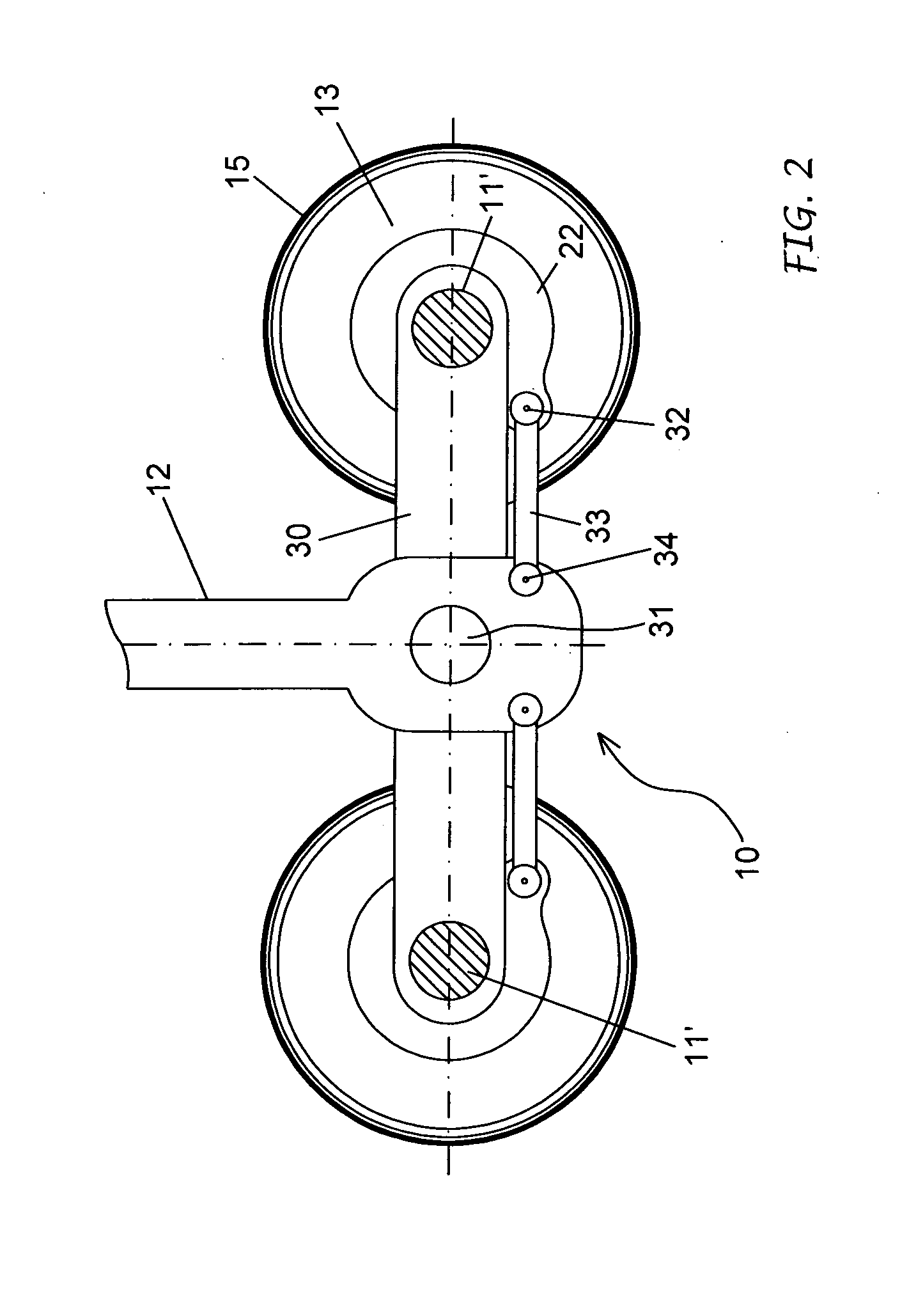
[0028]The system comprises a shaft 11, in this case not rotating, connected rigidly or integral with a supporting structure 12 of the carriage. On the shaft 11 is mounted, with the interposition of bearings 13′, a wheel rim 13 provided with an extension 14 to which is anchored a tyre 15. The wheel rim 13 is free to rotate compared to the shaft 11, whereas an opportune head cover 16 prevents the axial from sliding off the shaft.

[0029]Between the shaft 11 and the wheel rim 13 is provided a brake set with a rotor and a stator part.

[0030]The rotor ...


PUM


Abstract

The invention concerns a device and a method to cause the rotation of at least one wheel of the landing gear of aircraft, according to which between the supporting structure (12) of the landing gear and the brake group of the wheel is placed at least an actuator element with variable geometry (35) controlled and managed to develop such a force in order to impose an intermittent angular rotation of the wheel (15) when the brake group is operated.

Description

FIELD OF THE INVENTION[0001]This invention concerns the aircraft, in particular their landing gear and more precisely a device and a method to cause a rotation of the wheels of the landing gear at least for the movements on the ground of such vehicles.STATE OF THE TECHNIQUE[0002]The landing gear is a system that enables an aircraft to be supported when it is not flying, to amortize the energy from the contact with the ground during the landing phases and to facilitate the movements on the ground of the aircraft on the airport parking areas.[0003]The landing gear can be fixed or retractable; each with a single wheel or with one or more rows of coupled wheels and is equipped with a braking system. This consists more usually in disk brakes controlled hydraulically, housed inside the wheels of the landing gear. The is functions of the braking system are basically to: participate in the stopping operation of the aircraft during landing; to control its speed on the runway; to enable the a...

Claims


Application Information

Patent Timeline
Patent Type & Authority Applications(United States)
IPC IPC(8): B64C25/50
CPCY02T50/823B64C25/405Y02T50/80
Inventor GAIA, MARIO
Owner GAIA MARIO
Why Eureka
Try Eureka