Engine automatic control system

a technology of automatic control system and engine, which is applied in the direction of engine starters, process and machine control, instruments, etc., can solve the problems of engine starting possibility, low penetration rate of vehicle-to-vehicle communication apparatuses, and the possibility of engine starting, so as to reduce the useless consumption of fuel and improve fuel efficiency and manipulability.

Active Publication Date: 2012-02-02
DENSO CORP
View PDF0 Cites 56 Cited by
  • Summary
  • Abstract
  • Description
  • Claims
  • Application Information

AI Technical Summary

Benefits of technology

[0011]That is, the engine start determination section determines an engine start time in consideration of the display status of the traffic light, the state of the mobile object such as a subject vehicle, a different vehicle, and a pedestrian, which pass through an intersection. Therefore, in cases that although the display status of the traffic light is a green signal, a subject vehicle is in a state where the subject vehicle is unable to start forward movement, the engine start determination section determines the prohibition of starting an engine, for instance. That is, the engine start determination section continues the engine stop state until a time when the subject vehicle can start forward movement. The engine control section starts the engine when the engine start determination section permits the start of the engine. This enables the engine to be started at a suitable time, thereby reducing a useless consumption of fuel. Therefore, the fuel efficiency and manipulability can be improved further.

Problems solved by technology

The penetration rate of the vehicle-to-vehicle communications apparatuses is still low under the present circumstances; thus, the idling stop using the vehicle-to-vehicle communications has little practicality presently, posing a problem.
Thus, for example, even though the subject vehicle cannot start forward movement, there is a possibility that the engine may be started.
Such a case causes a useless fuel to be consumed to reduce a fuel efficiency, posing a problem.
In addition, if the determination of the engine start time is made based on the state of a preceding vehicle ahead of the subject vehicle, a time delay arises from when the preceding vehicle starts forward movement to when the subject vehicle starts forward movement.
This poses a problem to worsen a manipulability.

Method used


Image

  • Engine automatic control system
  • Engine automatic control system
  • Engine automatic control system

Examples


first embodiment

Modification of First Embodiment

[0049]An engine automatic control system 10 according to a modification of the first embodiment of the present invention is explained with reference to FIG. 5. The modification of the first embodiment is different from the first embodiment above mentioned in respect of an engine restart condition. The configuration and the flow of the processing of the engine automatic control system 10 according to the modification is similar to those of the first embodiment; thus, the explanation will be made also with reference to FIGS. 1 to 4. The modification of the first embodiment has a premise that the subject vehicle 40 is in a traffic light waiting state at the head of the vehicles waiting at the intersection. In such a case, the engine ECU 30 executes the engine automatic control process illustrated in FIG. 4 like in the first embodiment. At S101, the engine ECU 30 determines that no preceding vehicle exists ahead of the subject vehicle 40 based on the acqu...

second embodiment

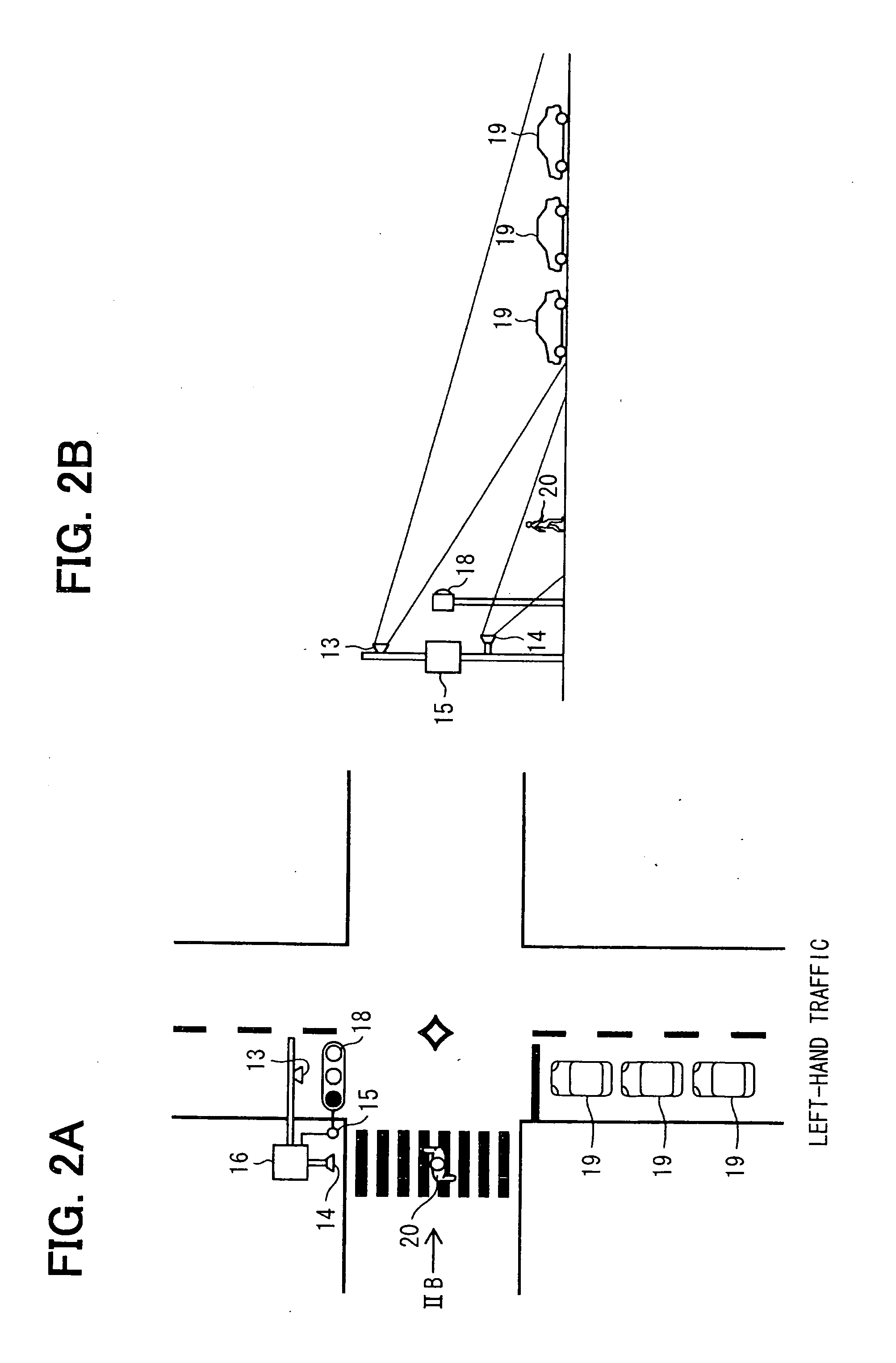
[0052]An engine automatic control system 10 according to a second embodiment of the present invention is explained with reference to FIGS. 6 (6A) to 11. Herein, the configuration and the flow of the processing of the engine automatic control system 10 according to the modification is almost similar to those of the first embodiment; thus, the explanation will be made also with reference to FIGS. 1 to 4. In the second embodiment, in cases that the subject vehicle 40 is waiting in an intersection so as to cross an oncoming (i.e., opposite) traffic lane to enter a cross road that intersects with a traveled road that the subject vehicle 40 traveled so far, the engine ECU 30 determines whether to permit an engine start depending on a presence of an oncoming vehicle in the oncoming traffic lane. This is equivalent to a circumstance where the subject vehicle 40 is in a right-turn waiting state in a left-hand traffic like in Japan or Great Britain, for instance as illustrated in FIG. 6A. Whe...

third embodiment

[0067]An engine automatic control system 10 according to a third embodiment of the present invention is explained with reference to FIG. 12. The configuration and the flow of the processing of the engine automatic control system 10 according to the third embodiment is similar to those of the first embodiment; thus, the explanation will be made also with reference to FIGS. 1, 4, and FIG. 7. The traffic light information received from the roadside apparatus 11 contains information on traffic light switchover time schedule as well as the traffic light state. In detail, the traffic light switchover time schedule of the traffic light information indicates, for instance, the green signal continuing for 30 seconds; the yellow signal then continuing for 2 seconds; the red signal then continuing for 30 seconds; and the green signal then continuing for 30 seconds, again. In addition, the traffic light information further contains information as to whether an auxiliary entrance permission sign...


PUM


Abstract

A roadside communicator in a roadside around an intersection transmits, to vehicles around the intersection, traffic light information on traffic light at the intersection and mobile object information on vehicles and pedestrians around the intersection. An in-vehicle communicator mounted in a subject vehicle acquires the traffic light information and the mobile object information. An in-vehicle engine start determination section mounted in the subject vehicle determines a permission or prohibition of a start of an engine of the subject vehicle based on the traffic light information and mobile object information. The engine start determination section determines an engine start time in consideration of a display of the traffic light, and states of mobile objects that pass through the intersection. An in-vehicle engine control section in the subject vehicle starts the engine when the engine start determination section permits the start of the engine.

Description

CROSS REFERENCE TO RELATED APPLICATION[0001]The present application is based on and incorporates herein by reference Japanese Patent Application No. 2010-173586 filed on Aug. 2, 2010.FIELD OF THE INVENTION[0002]The present invention relates to an engine automatic control system which automatically stops and starts an engine of a vehicle.BACKGROUND OF THE INVENTION[0003][Patent document 1] JP-2003-206781 A[0004][Patent document 2] JP-2001-207883 A[0005][Patent document 3] JP-2007-56734 A[0006][Patent document 4] JP-2006-316644 A[0007]In recent years, there is seen an idling stop, which stops an engine at a time when a vehicle stops, for a purpose of saving an energy and reducing an environmental load. In order to perform an idling stop effectively, it is necessary to appropriately designate a time for stopping an engine and a time for starting the engine. Such an engine stop time and an engine start time for a subject vehicle are determined conventionally based on so-called vehicle-t...

Claims


Application Information

Patent Timeline
Patent Type & Authority Applications(United States)
IPC IPC(8): G06F7/00
CPCF02N11/0837F02N2200/125Y02T10/48G08G1/096725G08G1/096783F02N2300/306Y02T10/40
Inventor NAGURA, MICHINAGAHASHIMOTO, NAOE
Owner DENSO CORP
Why Eureka
Try Eureka