
Engine automatic control system

a technology of automatic control system and engine, which is applied in the direction of engine starters, process and machine control, instruments, etc., can solve the problems of engine starting possibility, low penetration rate of vehicle-to-vehicle communication apparatuses, and the possibility of engine starting, so as to reduce the useless consumption of fuel and improve fuel efficiency and manipulability.

Active Publication Date: 2013-09-10
DENSO CORP
View PDF23 Cites 48 Cited by
  • Summary
  • Abstract
  • Description
  • Claims
  • Application Information

AI Technical Summary

Benefits of technology

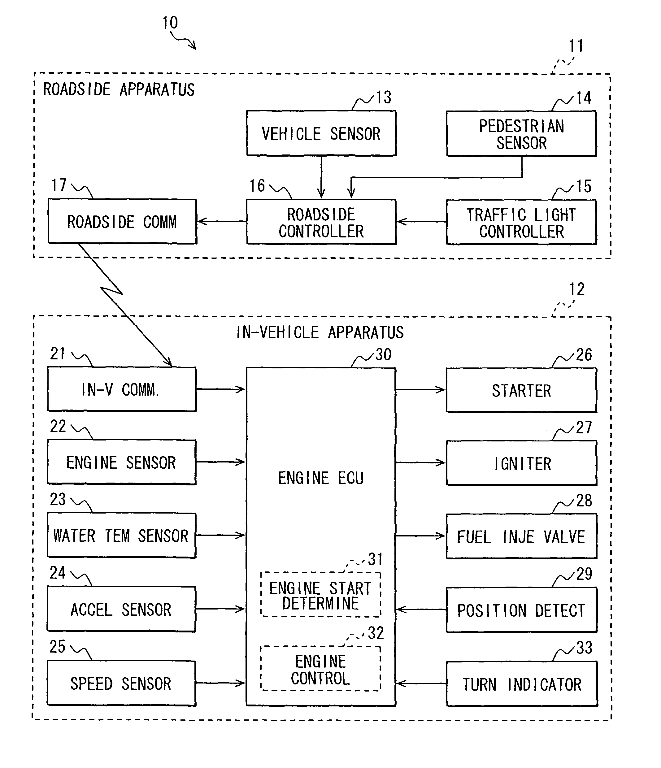
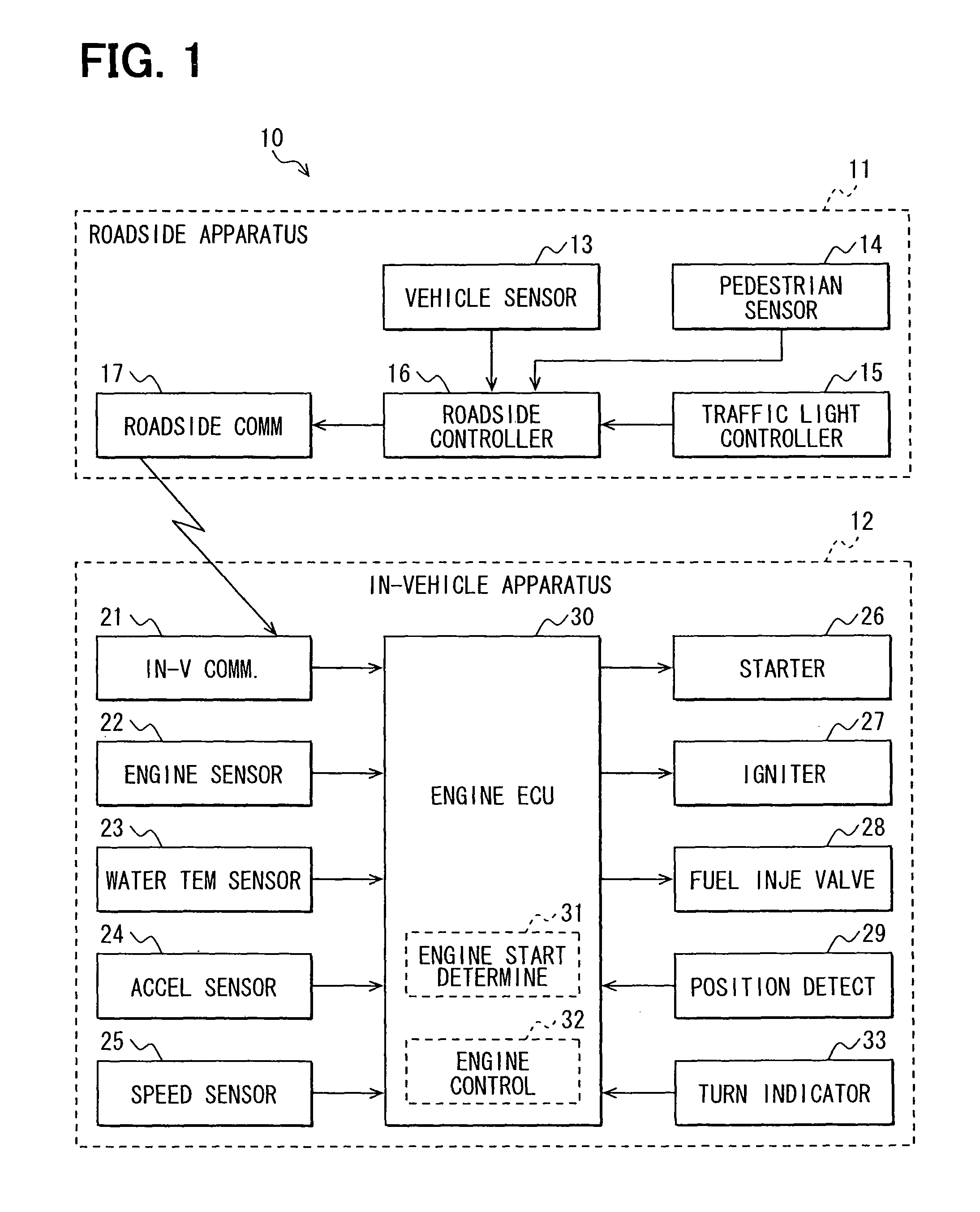
The present invention provides an engine automatic control system that improves fuel efficiency and manipulability by stopping or starting an engine of a vehicle at a suitable time based on the traffic state of an intersection. The engine start determination section takes into account the display status of the traffic light, the state of the mobile object such as a subject vehicle, a different vehicle, and a pedestrian, which pass through an intersection. The engine control section starts the engine when the engine start determination section permits the start of the engine, resulting in reduced fuel consumption and improved fuel efficiency and manipulability.

Problems solved by technology

The penetration rate of the vehicle-to-vehicle communications apparatuses is still low under the present circumstances; thus, the idling stop using the vehicle-to-vehicle communications has little practicality presently, posing a problem.
Thus, for example, even though the subject vehicle cannot start forward movement, there is a possibility that the engine may be started.
Such a case causes a useless fuel to be consumed to reduce a fuel efficiency, posing a problem.
In addition, if the determination of the engine start time is made based on the state of a preceding vehicle ahead of the subject vehicle, a time delay arises from when the preceding vehicle starts forward movement to when the subject vehicle starts forward movement.
This poses a problem to worsen a manipulability.

Method used


Image

  • Engine automatic control system
  • Engine automatic control system
  • Engine automatic control system

Examples


Embodiment Construction

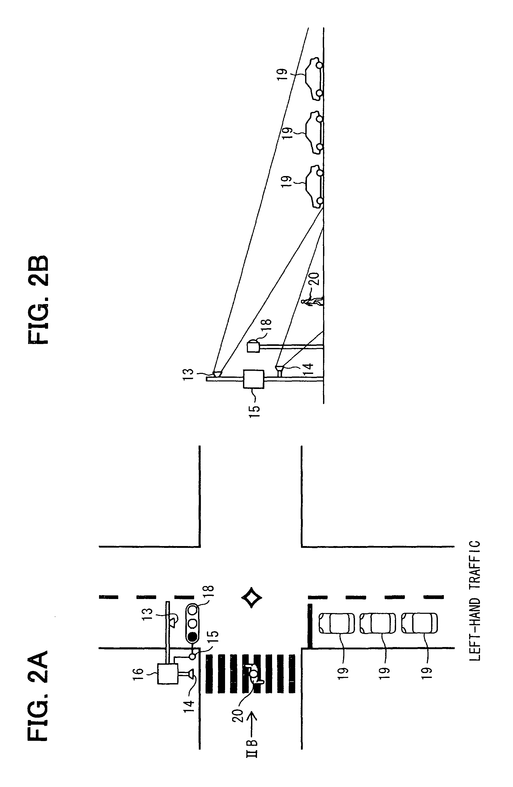
[0029]The following explains an engine automatic control system according to each of several embodiments of the present invention with reference to the drawings. In the present description, a pedestrian includes a person (i.e., a walking person) who exists around an intersection and a bicycle which exists around an intersection. In addition, in the present descriptions, an intersection or a traffic light device signifies an intersection or a traffic light device that is nearest from a subject vehicle that traveling a traffic lane of a road (also referred as a traveled road) in a heading direction, unless otherwise noted. Further, for instance, an intersection is formed by (i) a traveled road, which a subject vehicle traveled just up to the present time, and (ii) a cross road that intersects with the traveled road. Furthermore, an intersection is defined as containing pedestrians' crosswalks that cross over the traveled road or the cross road around the intersection. In the embodimen...


PUM


Abstract

A roadside communicator in a roadside around an intersection transmits, to vehicles around the intersection, traffic light information on traffic light at the intersection and mobile object information on vehicles and pedestrians around the intersection. An in-vehicle communicator mounted in a subject vehicle acquires the traffic light information and the mobile object information. An in-vehicle engine start determination section mounted in the subject vehicle determines a permission or prohibition of a start of an engine of the subject vehicle based on the traffic light information and mobile object information. The engine start determination section determines an engine start time in consideration of a display of the traffic light, and states of mobile objects that pass through the intersection. An in-vehicle engine control section in the subject vehicle starts the engine when the engine start determination section permits the start of the engine.

Description

CROSS REFERENCE TO RELATED APPLICATION[0001]The present application is based on and incorporates herein by reference Japanese Patent Application No. 2010-173586 filed on Aug. 2, 2010.FIELD OF THE INVENTION[0002]The present invention relates to an engine automatic control system which automatically stops and starts an engine of a vehicle.BACKGROUND OF THE INVENTION[0003][Patent document 1] JP-2003-206781 A[0004][Patent document 2] JP-2001-207883 A[0005][Patent document 3] JP-2007-56734 A[0006][Patent document 4] JP-2006-316644 A[0007]In recent years, there is seen an idling stop, which stops an engine at a time when a vehicle stops, for a purpose of saving an energy and reducing an environmental load. In order to perform an idling stop effectively, it is necessary to appropriately designate a time for stopping an engine and a time for starting the engine. Such an engine stop time and an engine start time for a subject vehicle are determined conventionally based on so-called vehicle-t...

Claims


Application Information

Patent Timeline
Patent Type & Authority Patents(United States)
IPC IPC(8): F02D29/02F02N11/08G08G1/0967
CPCF02N11/0837G08G1/096725G08G1/096783F02N2200/125F02N2300/306Y02T10/48Y02T10/40
Inventor NAGURA, MICHINAGAHASHIMOTO, NAOE
Owner DENSO CORP
Learn More