Fail-passive variable gradient control stick drive system

a control stick and gradient technology, applied in the direction of control initiation means, aircraft components, power plants, etc., can solve the problem that conventional control technologies using mechanical linkages cannot relieve the pilot of higher mental and manual control activity

Active Publication Date: 2012-06-28
WOODWARD MPC
View PDF7 Cites 20 Cited by
  • Summary
  • Abstract
  • Description
  • Claims
  • Application Information

AI Technical Summary

Benefits of technology

[0022]In some embodiments, the use of the passive feedback arrangement allows the system to be an indirect system. More particularly, the positioning arrangement is indirectly coupled to the stick via the passive feedback arrangement such that the stick can move relative to the mechanical ground independent of movement of the positioning arrangement. This provides a benefit of providing a ...

Problems solved by technology

As the performance requirements of both civil and military aircraft increases, conventional control te...

Method used


Image

  • Fail-passive variable gradient control stick drive system
  • Fail-passive variable gradient control stick drive system
  • Fail-passive variable gradient control stick drive system

Examples


Embodiment Construction

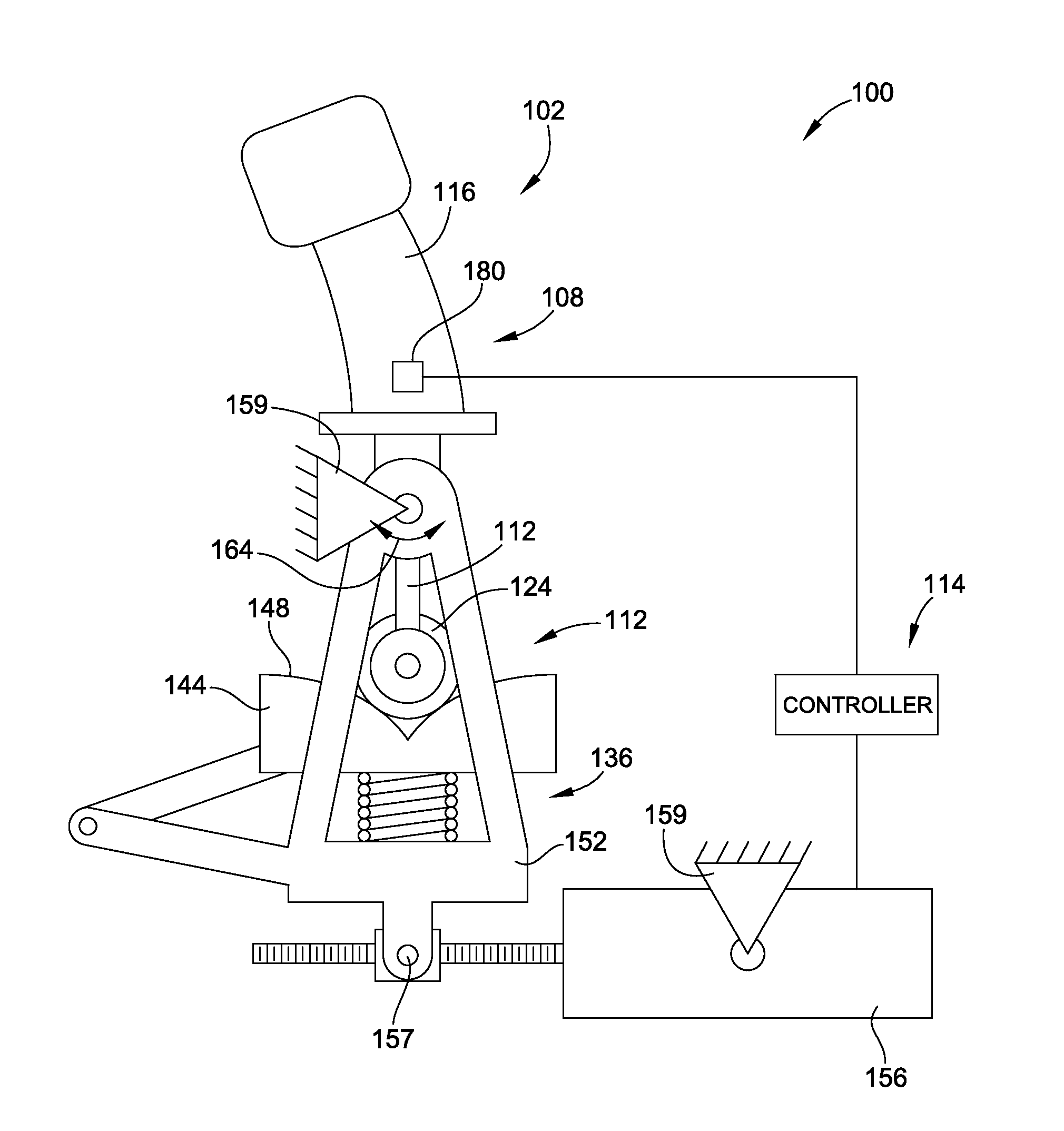
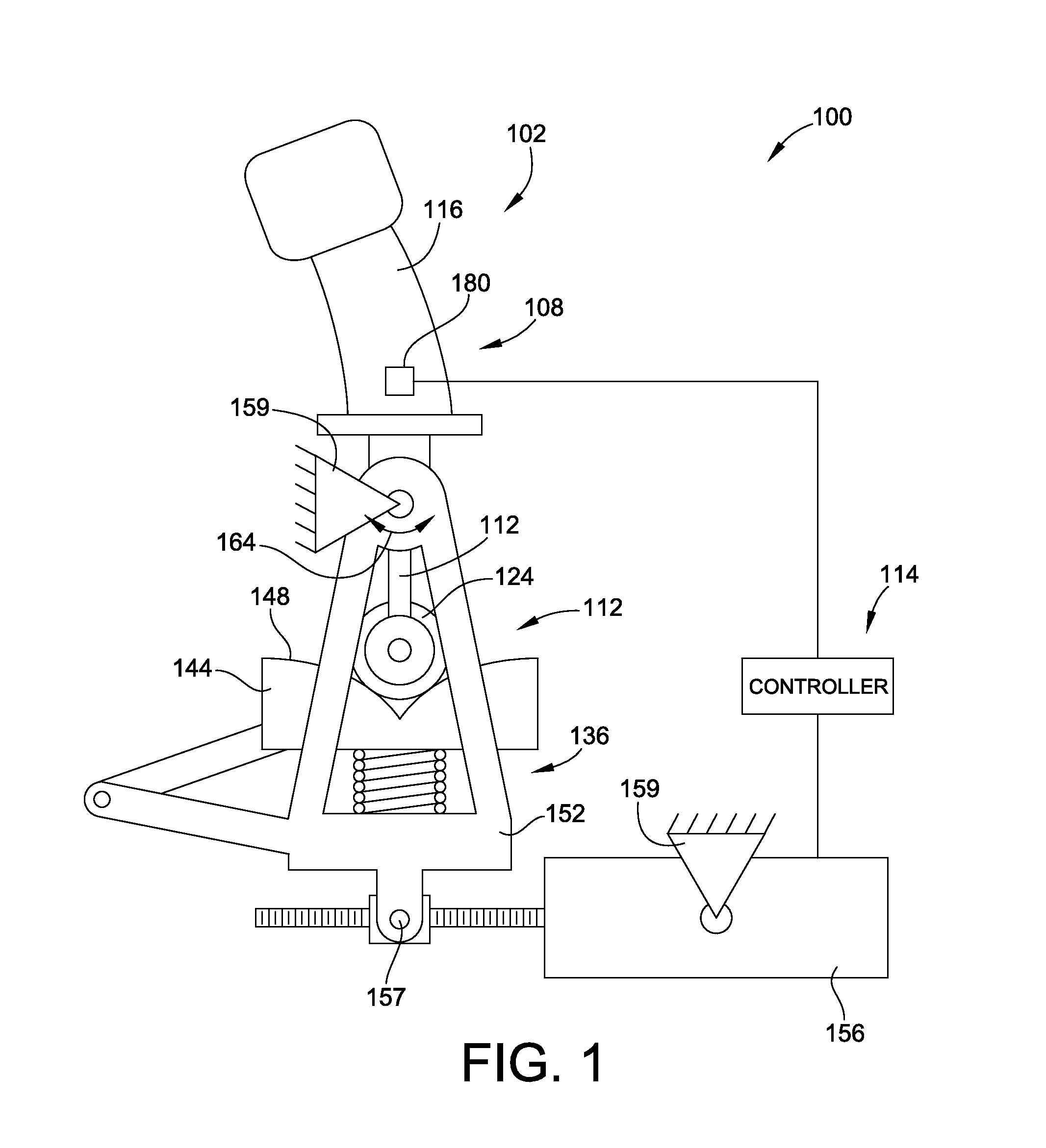
[0043]FIG. 1 is a simplified schematic illustration of an aircraft control system 100 for controlling pitch, roll or both pitch and roll of an aircraft. The aircraft control system 100 generally includes control column 102. The control column 102 is used by the pilot to control various operation of the aircraft such as pitch, roll and / or pitch and roll.

[0044]The control column 102 is considered fly-by-wire control columns because the manipulation of the control column to adjust the pitch and / or roll of the aircraft is not translated directly to the control surfaces of the aircraft by mechanical devices. Instead, the deviations of the control column from a neutral position are sensed and then converted into electrical signals. These signals are then sent to actuators which use the electrical signals to make proportional changes in the control surfaces of the aircraft.

[0045]Because the control column 102 is not mechanically linked to the control surfaces, the control system 100 incorp...


PUM


Abstract

A control system for an aircraft including a passive feedback arrangement, a stick and a positioning arrangement is provided that provides for user adjustability of the resistance applied to the stick, such as in a fly-by-wire system. The passive feedback arrangement is movable relative to a mechanical ground. The stick is moveable relative to the mechanical ground and the passive feedback arrangement. The passive feedback arrangement acts on the stick to resist movement of the stick relative to the passive feedback arrangement. This resistance provides passive feedback to the pilot for the fly-by-wire system. The positioning arrangement is coupled to the passive feedback arrangement for adjusting the position of the passive feedback arrangement relative to the mechanical ground in response to movement of the stick relative to the mechanical ground.

Description

FIELD OF THE INVENTION[0001]This invention generally relates to control sticks for aircrafts and more particularly to fly-by-wire control sticks for aircrafts.BACKGROUND OF THE INVENTION[0002]As the performance requirements of both civil and military aircraft increases, conventional control technologies using mechanical linkages cannot relieve the pilot from higher mental and manual control activity. As such, today's high performance aircraft as well as some transport aircraft use “fly-by-wire” sidesticks, center sticks, yokes, joysticks and control columns. As used herein, these devices will be generically referred to either “control columns” or “control sticks,” with these terms being generally synonymous in a generic sense.[0003]These fly-by-wire control columns simulate tactile feedback relating to the forces acting on the control surfaces of the aircraft to the control columns.[0004]In a “passive” control column, the pilot feels spring or damper forces according to the applied ...

Claims


Application Information

Patent Timeline
IPC IPC(8): B64C13/46B64C13/50
CPCB64C13/02
Inventor SCOTT, CRAIGSTACHNIAK, DARRYL S.
Owner WOODWARD MPC
Why Eureka
Try Eureka