Control system for simplifying control of a model railroad

a control system and model railroad technology, applied in the field of model railroading, can solve the problems of not being user-friendly, not very convenient to use, and being difficult to understand and operate by users, and achieve the effect of simplifying set up and us

Active Publication Date: 2012-06-28
RING TIMOTHY W
View PDF28 Cites 2 Cited by
  • Summary
  • Abstract
  • Description
  • Claims
  • Application Information

AI Technical Summary

Benefits of technology

[0012]Still another object of the present invention is to provide an apparatus and method for all system components to have the ability to hold configuration data making them all “smart components” which allows for simplified set up and use.
[0013]Yet another object of the invention is to provide a means of protecting system components by password protection to keep other system users from accidentally controlling things they should not or to isolate particular controlled devices to specific users in a multi user environment.
[0014]A further object of the invention is to provide a means to allow multiple controllers and multiple controlled devices without the need for a master controller to provide coordination.

Problems solved by technology

Many improvements have been made making the model railroad more realistic, however all have been typically complex as well as difficult for users to understand and operate.
The use of digital technology has added a layer of complexity for the model railroad operator; however it has greatly enhanced the realism which can be attained with model railroad trains and accessories.
Prior to the present invention, these hand held devices all use cryptic throttles, button type keypads, text based displays, and user interfaces that are not user friendly and not very convenient to use.
With these types of controllers and accessories, a reasonably educated user with knowledge of electricity, some exposure to digital electronics as well as some knowledge and use of computers would still find these units difficult to initialize, configure and operate.

Method used


Image

  • Control system for simplifying control of a model railroad
  • Control system for simplifying control of a model railroad
  • Control system for simplifying control of a model railroad

Examples


Embodiment Construction

[0042]Prior to proceeding to the more detailed description of the present invention, it should be noted that, for the sake of clarity and understanding, identical components which have identical functions have been identified with identical reference numerals throughout the several views illustrated in the drawing figures.

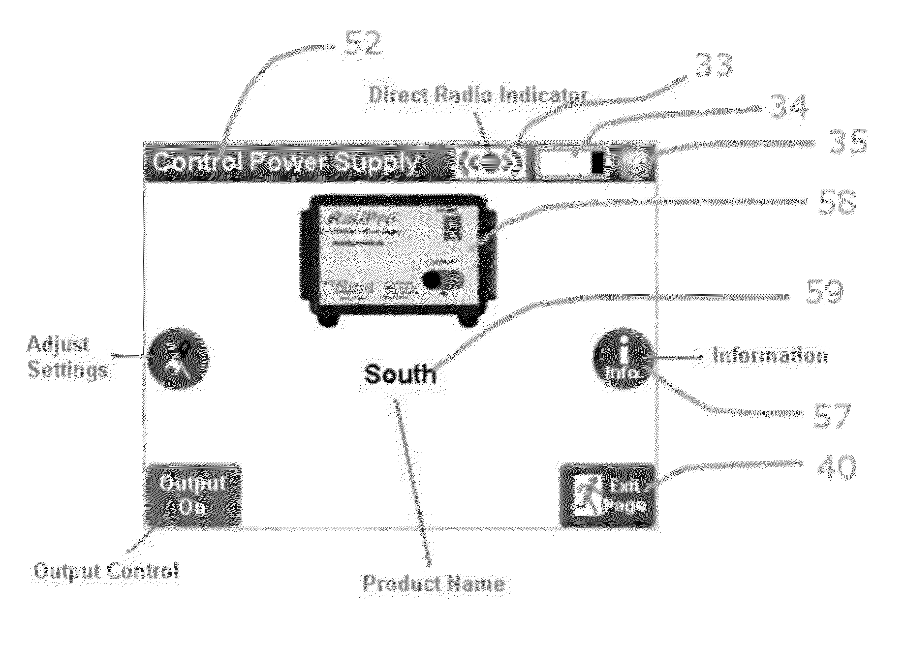
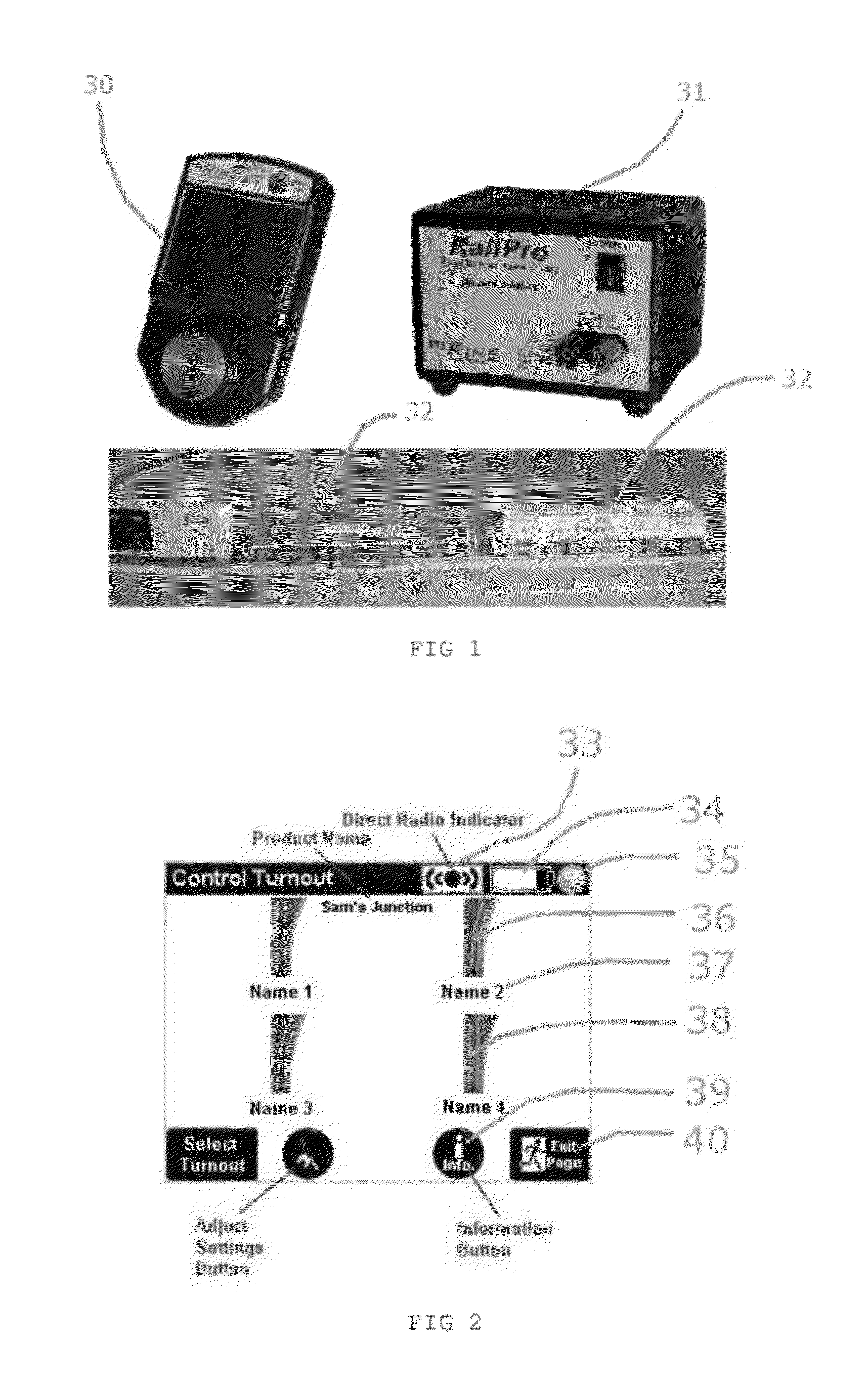
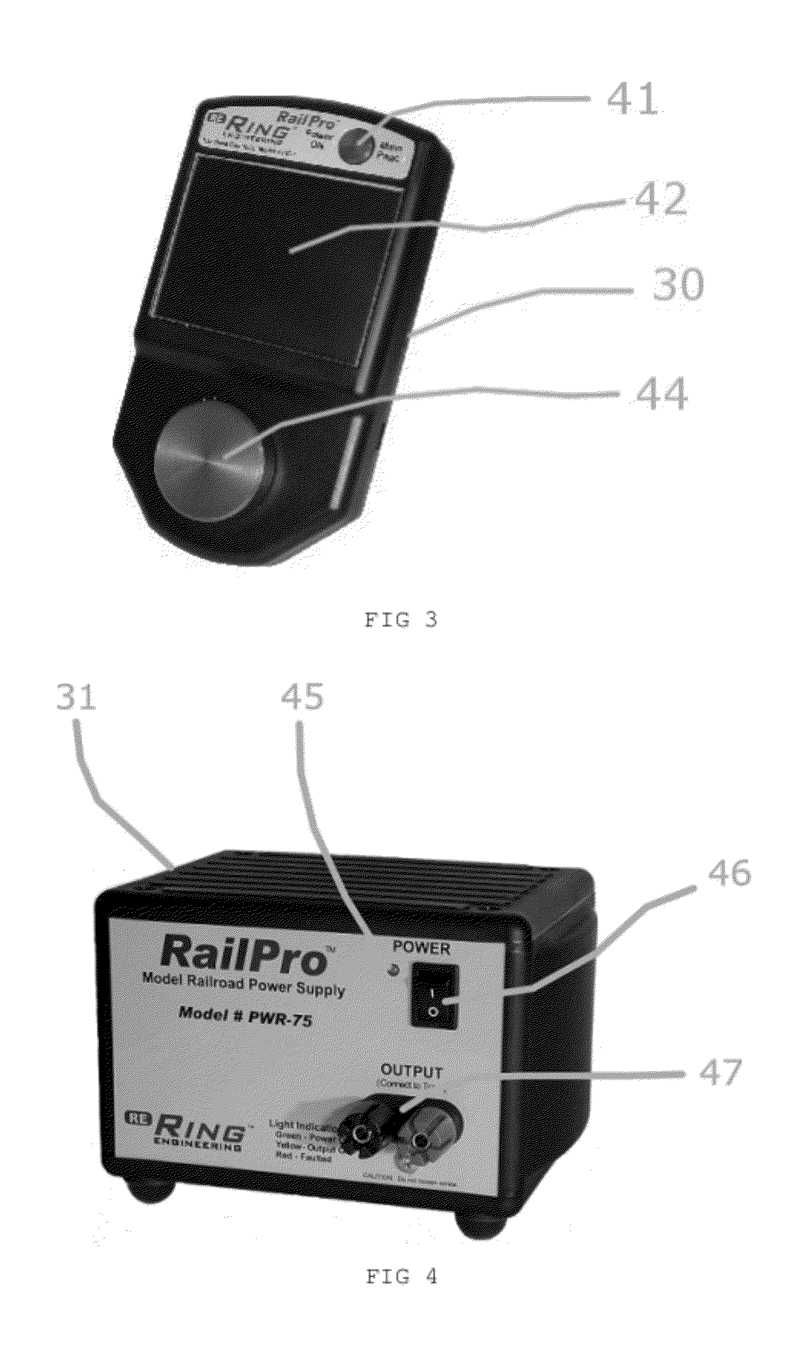
[0043]With that, the presently preferred invention of the control system for controlling operation of at least a pair of motor powered rail vehicles, or locomotives 32, consists of at least one hand held control device or controller 30, at least one power supply 31, and at least one control module 87 that may be used to control any model railroad accessory or locomotive. The controller 30 is also referred in this document as a “throttle”. Although many other configurations can exist, this minimal number of devices provides the most basic system for ease of explanation, although more complex systems can exist.

[0044]The presently preferred simplified control system m...


PUM


Abstract

A control system for at least a pair of motor powered rail vehicles coupled together in a model train railroad includes a controller, a control module installed on each of the at least pair of motor powered rail vehicles, a bi-directional communication between the controller and at least one control module in one of the at least pair of motor powered rail vehicles, a bi-directional communication between the at least pair of control modules, and at least one of the controller and the one of the pair of control modules configured to store in memory full load electrical power value and use the full load electrical power value in adjusting motor load for a respective motor powered rail vehicle. The control system also uses a subsonic motor signal to enhance low speed operation of rail vehicles and a graphical interface within the controller and capability to utilize previously unknown devices.

Description

CROSS-REFERENCE TO RELATED APPLICATIONS[0001]This application is related to and claims priority from U.S. Provisional Patent Application Ser. No. 61 / 427,294 filed on Dec. 27, 2010.FIELD OF THE INVENTION[0002]This invention relates, in general to model railroading and, more particularly, the invention relates to a means for simplifying the control of energy that causes action, lights, sound, movement of trains, and operation of accessories in a model railroad environment.STATEMENT REGARDING FEDERALLY SPONSORED RESEARCH AND DEVELOPMENT[0003]N / AREFERENCE TO SEQUENCE LISTING, A TABLE, OR A COMPUTER PROGRAM LISTING COMPACT DISC APPENDIX[0004]N / ABACKGROUND OF THE INVENTION[0005]The model railroad industry, as is well recognized in the art, has always sought additional ways to make model trains and associated accessories operate as realistically as possible. Many improvements have been made making the model railroad more realistic, however all have been typically complex as well as difficu...

Claims


Application Information

Patent Timeline
Patent Type & Authority Applications(United States)
IPC IPC(8): B61L3/18G06F19/00
CPCA63H19/24
Inventor RING, TIMOTHY W.
Owner RING TIMOTHY W
Why Eureka
Try Eureka