Touch Surface With A Compensated Signal Profile

a signal profile and touch surface technology, applied in the field of touch surface with a compensated signal profile, can solve the problems of costly known ftir techniques, and achieve the effects of simple and efficient data processing, reduced impact, and accurate determination of the location of objects

Inactive Publication Date: 2012-06-28
FLATFROG LAB
View PDF15 Cites 105 Cited by
  • Summary
  • Abstract
  • Description
  • Claims
  • Application Information

AI Technical Summary

Benefits of technology

[0012]An advantage of the invention may lie in a reduced impact of e.g. contaminations and damages / imperfections of the touch surface when determining the location of the object; by intermittently updating the background signal profile, signal features originating for contaminations / damages / imperfections will be automatically suppressed or even eliminated in the compensated signal profile. As a result, a more accurate determination of the location of the object can be obtained by comparatively simple and efficient data processing. Moreover, the inventive apparatus is particularly suitable when the determining of the location of the object is based on attenuation of light and the hence relatively complex current signal profile of the received light. In particular, in case the internal reflections in the panel are caused by total (or almost total) internal reflection (TIR) and the touch of the object causes FTIR, the apparatus has been found surprisingly promising in respect of efficiently processing the obtained signal profiles.
[0013]The apparatus is also suitable for handling situations where contaminations are removed from the touch surface, which typically results in a decreased attenuation at the location of the removed contamination. In this case the updating of the background signal profile can be seen as “negative” in comparison with the situation when contamination is added to the touch surface.
[0014]The processor unit can be seen as means for performing the iterative process and, during the iterative process, means for determining the current signal profile, updating the background signal profile, calculating the compensated signal profile and determining the location of the object. Also, as the skilled person realizes, the processor unit can comprise one or more data processors which each performs one or more of the described processing operations.
[0015]As indicated, the processor unit performs an iterative operation for determining the location of the object touching the touch surface. Moreover, the iteration can be continuously performed irrespectively if the object touches the touch surface. Also, operations of the processor unit may be performed in a different order than described, may be combined and may be divided into sub-operations. Furthermore, additional operations may be performed by the processor unit and certain operations can be performed only when the processor unit determines that an object touches the touch surface.
[0016]Here, light is referred to as electromagnetic radiation with a wavelength selected within the range of 10 nm to 1 mm, i.e. both ultraviolet, visible and infra-red light can be used for the detection of the location of the object, though infra-red light is often the most preferable light.
[0017]The processor unit may be configured to calculate the compensated signal profile by dividing the current signal profile with the background signal profile. By configuring the processor unit in this manner the compensated signal profile can be seen as a so-called transmission signal. The transmission signal can have an essentially uniform signal level at a (relative) transmission of about one with a local decline in the signal profile when the object touches the touch surface.

Problems solved by technology

These known FTIR techniques suffer from being costly, i.a. since they require the use of a relatively complex devices for measuring the light with such an accuracy that it is possible to satisfactory differentiate objects touching the panel from other, irrelevant objects possibly present on the panel.
However, it does not necessarily mean that this updating (when object touches the surface) is triggered by the touch, even if it is possible.

Method used


Image

  • Touch Surface With A Compensated Signal Profile
  • Touch Surface With A Compensated Signal Profile
  • Touch Surface With A Compensated Signal Profile

Examples


Embodiment Construction

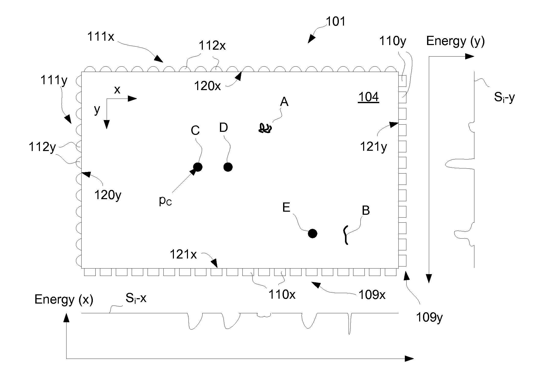
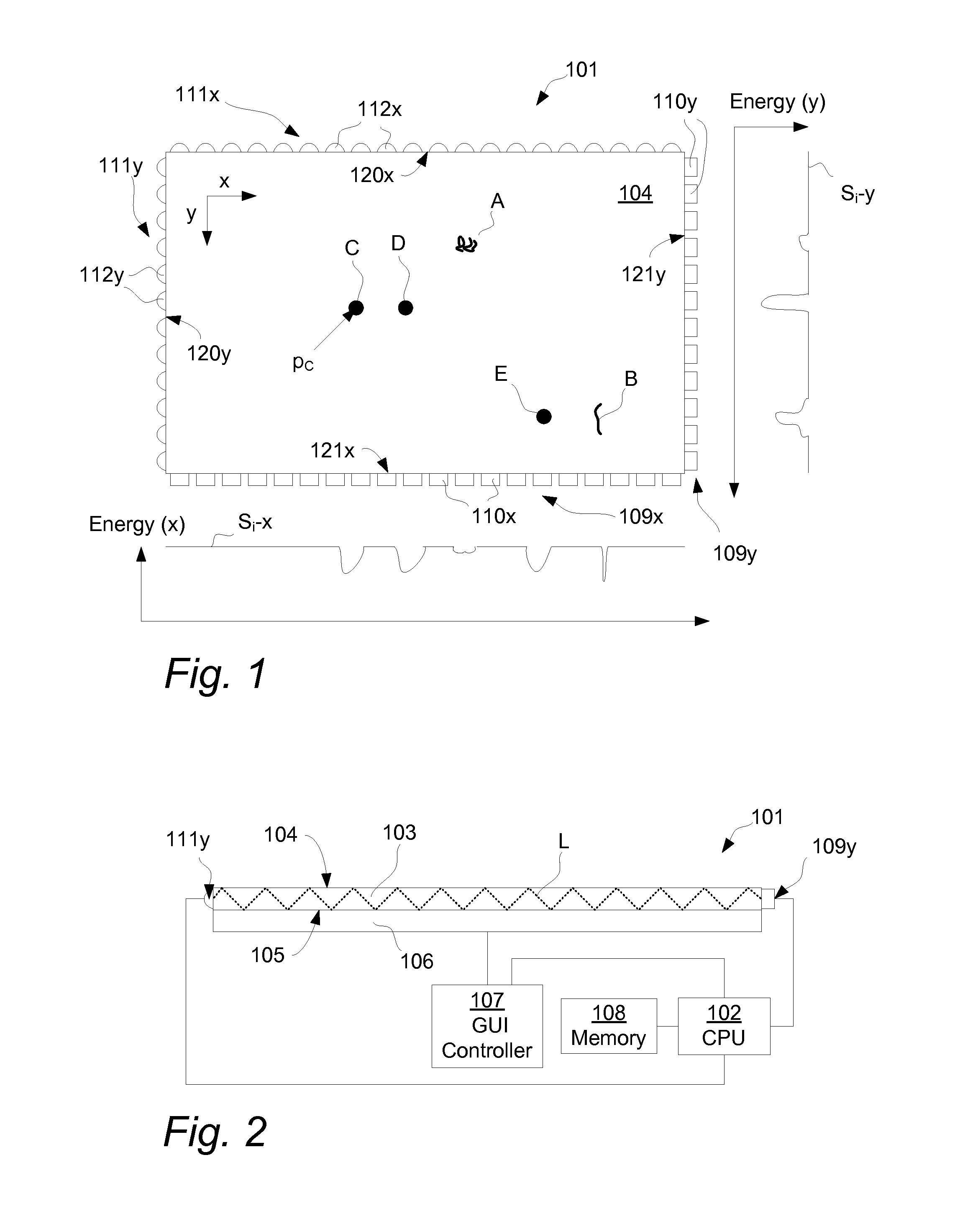
[0059]FIGS. 1-2 illustrate an embodiment of a touch-sensing apparatus 101 that includes a light transmissive panel 103. The panel 103 may be planar or curved and defines a touch surface 104 and an opposite surface 105 opposite and generally parallel with the touch surface 104. The panel 103 is configured to allow light L to propagate inside the panel 103 by internal reflection and can have the shape of e.g. a rectangular, circular and elliptical plane.

[0060]Hence, a light propagation channel is provided between the touch surface 104 and the opposite surface 105 which in combination form two boundary surfaces of the panel 103. The touch surface 104 allows the propagating light L to interact with one or more touching objects (three objects C, D, E are shown) in the form of e.g. a finger or stylus. A contamination on the touch surface 104 in the form of a fingerprint A as well as a damage on the touch surface 104 in form of a scratch B are also illustrated. Here, the damage B can be re...


PUM


Abstract

An apparatus, method and computer-readable medium for determining a location of at least one object on a touch surface of a light transmissive panel. The method comprises the steps of: introducing light into the panel for propagation by internal reflection between the touch surface and an opposite surface; receiving the light propagating in the panel; and iteratively i) determining a current signal profile of light received by the light detection arrangement, ii) updating, when a condition is met, a background signal profile of light received by the light detection arrangement, iii) calculating a current compensated signal profile as a function of the background signal profile and the current signal profile and iv) determining, when the object touches the touch surface and thereby attenuates the light propagating in the panel, the location as a function of the compensated signal profile.

Description

CROSS-REFERENCE TO RELATED APPLICATIONS[0001]The present application claims the benefit of Swedish patent application No. 0950628-8, filed 2 Sep. 2009, U.S. provisional application No. 61 / 272,219, filed 2 Sep. 2009, Swedish patent application No. 0950767-4, filed 19 Oct. 2009, and U.S. provisional application No. 61 / 272,666, filed 19 Oct. 2009, which all are incorporated by reference.TECHNICAL FIELD[0002]The invention relates to techniques for detecting the location of an object on a touch surface. The touch surface may be part of a touch-sensitive panel.BACKGROUND ART[0003]To an increasing extent, touch-sensitive panels are being used for providing input data to computers, electronic measurement and test equipment, gaming devices, etc. The panel may be provided with a graphical user interface (GUI) for a user to interact with using e.g. a pointer, stylus or one or more fingers. The GUI may be fixed or dynamic. A fixed GUI may e.g. be in the form of printed matter placed over, under...

Claims


Application Information

Patent Timeline
Patent Type & Authority Applications(United States)
IPC IPC(8): G06F3/041
CPCG06F3/0418G06F2203/04109G06F3/0421G06F3/0304
Inventor FAHRAEUS, CHRISTERCHRISTIANSSON, TOMASWALL, HENRIKWASSVIK, OLA
Owner FLATFROG LAB
Why Eureka
Try Eureka