Driving method of liquid crystal display device

Inactive Publication Date: 2012-06-28
SEMICON ENERGY LAB CO LTD
View PDF17 Cites 12 Cited by
  • Summary
  • Abstract
  • Description
  • Claims
  • Application Information

AI Technical Summary

Benefits of technology

[0011]In a driving method of a liquid crystal display device according to one embodiment of the present invention, input of image signals to part of a plurality of pixels included in a particular region of a pixel portion and supply of light to part of another plurality of pixels which is different from the part are performed concurrently. Therefore, it is not necessary to provide a period in which light is supplied to all of the plurality of pixels included in the region after the image signals are input thereto. In other words, it is possible to start input of the next image signals to all of the plurality of pixels included in the region just after the image signals are input thereto. Accordingly, in the driving method of the liquid crystal display device according to one embodiment of the present invention, it is possible to increase the input frequency of the image signals. Thus, it is possible to increase the frame frequency in the liquid crystal display device. As a result, it is possible to suppress changes (deterioration) of display caused in a field-sequential liquid crystal display device. Note that the increase of the frame frequency in the field-sequential liquid crystal display device has an advantageous effect of suppressing occurrence of the above-described static color break and dynamic color break.
[0012]In addition, in a driving method of a liquid crystal display device according to one embodiment of the present invention, two images which are sequentially displayed are formed by a different supply order of light. Accordingly

Problems solved by technology

Therefore, lack of given display data caused by block of display in a short time (e.g., blink of the user) might occur.
In addition, display data in consecutive frames l

Method used


Image

  • Driving method of liquid crystal display device
  • Driving method of liquid crystal display device
  • Driving method of liquid crystal display device

Examples


modification example

[0096]The liquid crystal display device described above is one embodiment of the present invention, and the present invention includes a liquid crystal display device which is different from the above-described liquid crystal display device.

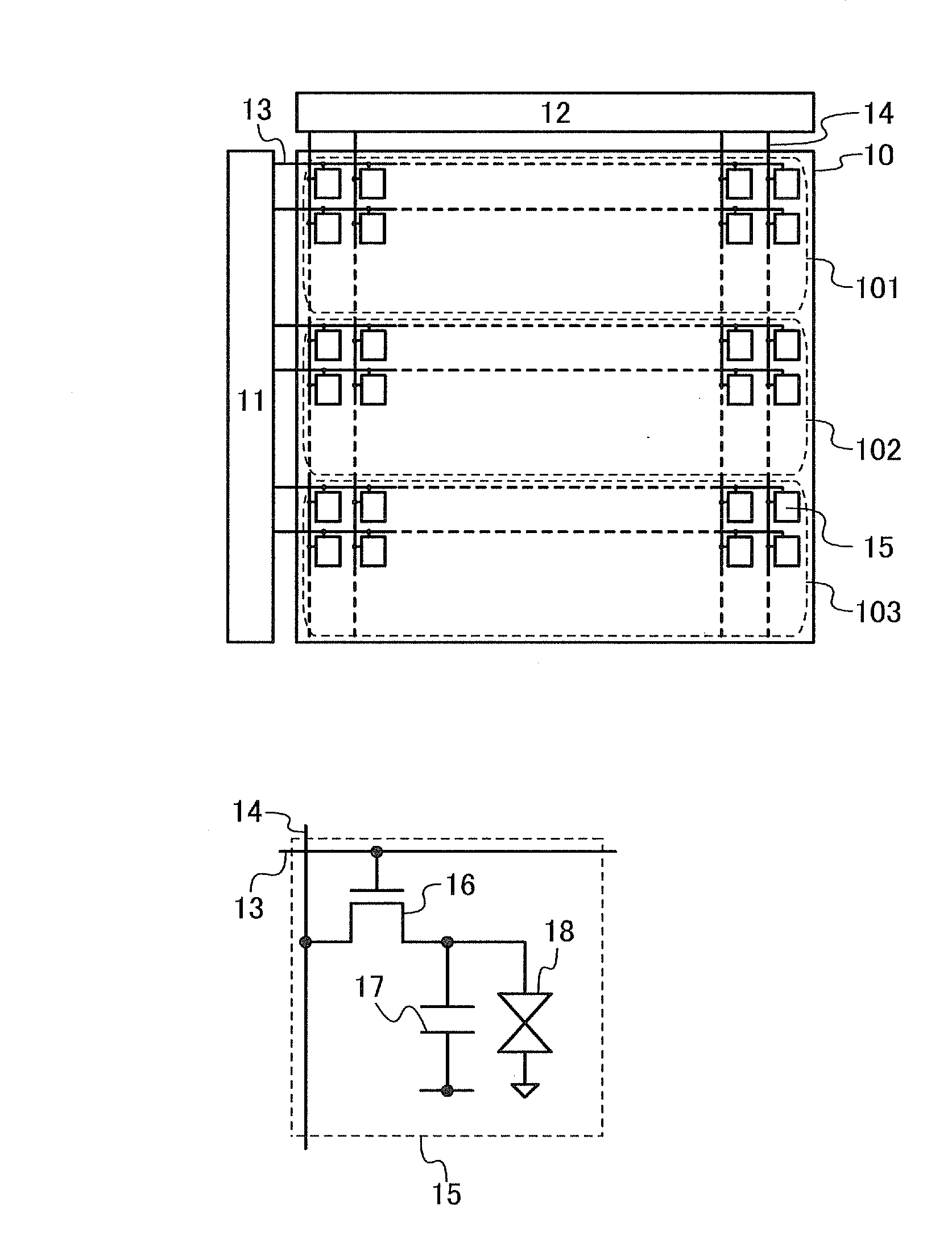
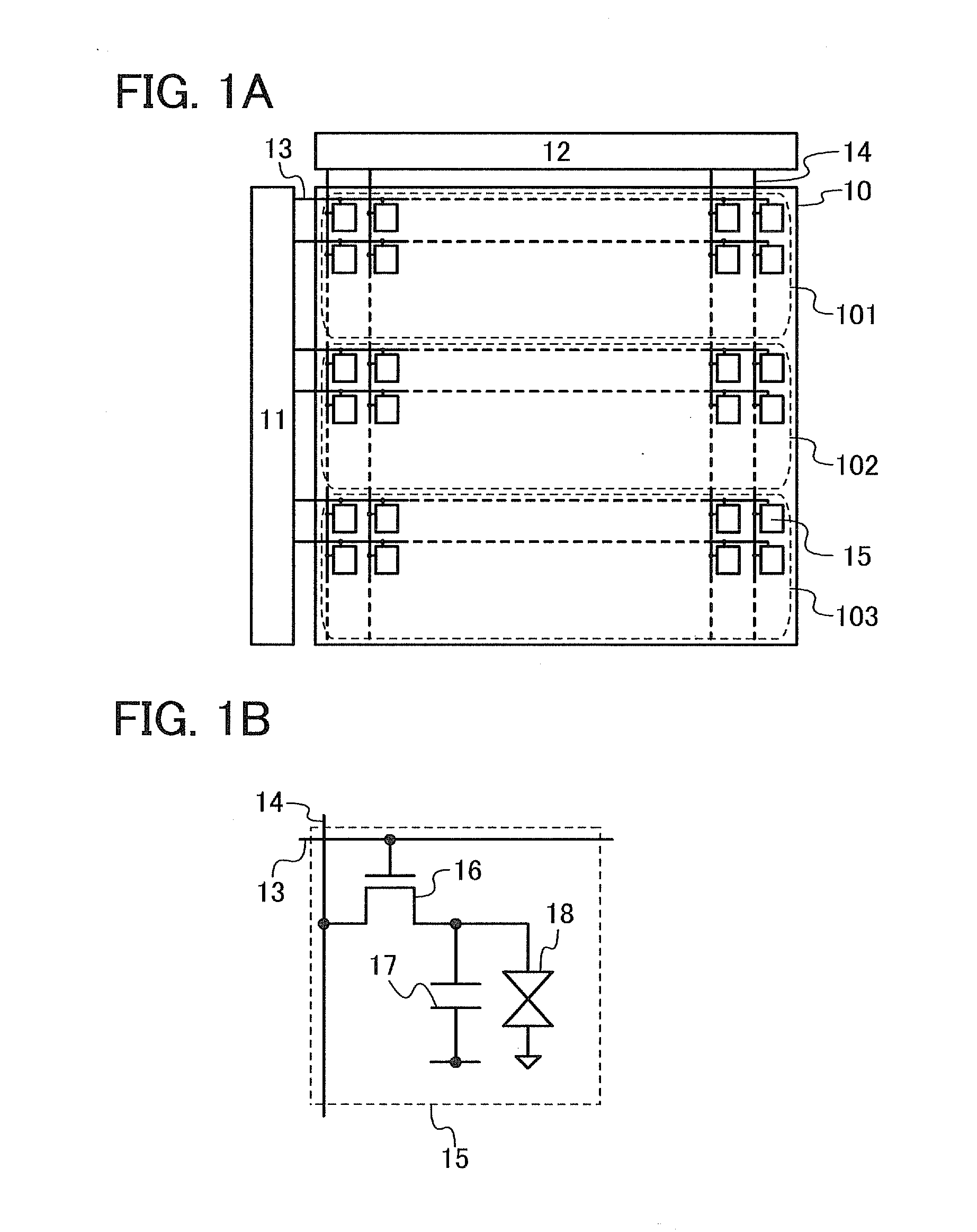
[0097]For example, the liquid crystal display device described above has a structure in which the pixel portion 10 is divided into three regions and the image signals are supplied concurrently to the three regions; however, a liquid crystal display device according to one embodiment of the present invention is not limited to the structure. In other words, the liquid crystal display device according to one embodiment of the present invention can have a structure in which the pixel portion 10 is divided into a plurality of regions the number of which is not three and the image signals are supplied concurrently to the respective plurality of regions. In the case where the number of regions is changed, it is necessary to set clock signals for the sca...

specific example

[0110]A specific example of the above-described liquid crystal display device will be described below.

[0111]FIG. 12A is a top view of a structure example of a pixel of the above-described liquid crystal display device, and FIG. 12B is a cross-sectional view taken along line A-A′ and line B-B′ in FIG. 12A.

[0112]The pixel illustrated in FIG. 12A includes a scan line 801, a signal line 802, a common potential line 803, a capacitor line 804, a transistor 805, a pixel electrode 806, a common electrode 807, and a capacitor 808. In addition, these components are formed using a first conductive layer 851, a semiconductor layer 852, a second conductive layer 853, and a third conductive layer 854 (also referred to as a transparent electrode layer) each of which is obtained in such a way that a thin film formed over the entire surface of a substrate is separated and processed into a plurality of layers.

[0113]Specifically, the scan line 801, a gate electrode of the transistor 805, and one elect...


PUM


Abstract

Input of image signals to part of a plurality of pixels included in a particular region of a pixel portion and supply of light to part of another plurality of pixels which is different from the part are performed concurrently. Therefore, it is not necessary to provide a period in which light is supplied to all of the plurality of pixels included in the region after the image signals are input thereto. In other words, it is possible to start input of the next image signals to all of the plurality of pixels included in the region just after the image signals are input thereto. Accordingly, it is possible to increase the input frequency of the image signals. As a result, it is possible to suppress deteriorations of display caused in the field-sequential liquid crystal display device.

Description

BACKGROUND OF THE INVENTION[0001]1. Field of the Invention[0002]The present invention relates to a method for driving a liquid crystal display device. In particular, the present invention relates to a driving method of a field-sequential liquid crystal display device.[0003]2. Description of the Related Art[0004]A color filter method and a field sequential method are known as display methods for liquid crystal display devices. In a color-filter liquid crystal display device, a plurality of subpixels which has color filters for transmitting only light with a given wavelength is provided in each pixel. A desired color is produced in such a manner that transmission of white light is controlled in each subpixel and a plurality of colors is mixed in each pixel. In contrast, in a field-sequential liquid crystal display device, a plurality of light sources that emit light of different colors is provided. A desired color is produced in such a manner that lighting of the plurality of light so...

Claims


Application Information

Patent Timeline
IPC IPC(8): G09G3/36G09G5/10
CPCG09G3/3413G09G3/342G09G3/3677G09G2320/0261G09G2320/0242G09G2320/0247G09G2310/0235G09G3/36
Inventor MIYAIRI, HIDEKAZUMIYAKE, HIROYUKITOYOTAKA, KOUHEIKAWASHIMA, SUSUMU
Owner SEMICON ENERGY LAB CO LTD
Why Eureka
Try Eureka