
Image processing device and image display device

a technology of image processing and display device, which is applied in the field of electronic device operation, can solve the problems of device according and difficult operation by users, and achieve the effect of improving user's usability of electronic units and efficient operation of electronic units

Active Publication Date: 2012-06-28
MAXELL HLDG LTD
View PDF3 Cites 32 Cited by
  • Summary
  • Abstract
  • Description
  • Claims
  • Application Information

AI Technical Summary

Benefits of technology

[0009]The above-mentioned means enables efficient operations of the electronic units by the gesture and improves user's usability of the electronic units.

Problems solved by technology

The device according to the technical idea of the Patent Document 1, however, is not easy for users to operate, since pre-registered gestures need to be stored in electronic units.

Method used


Image

  • Image processing device and image display device
  • Image processing device and image display device
  • Image processing device and image display device

Examples


first embodiment

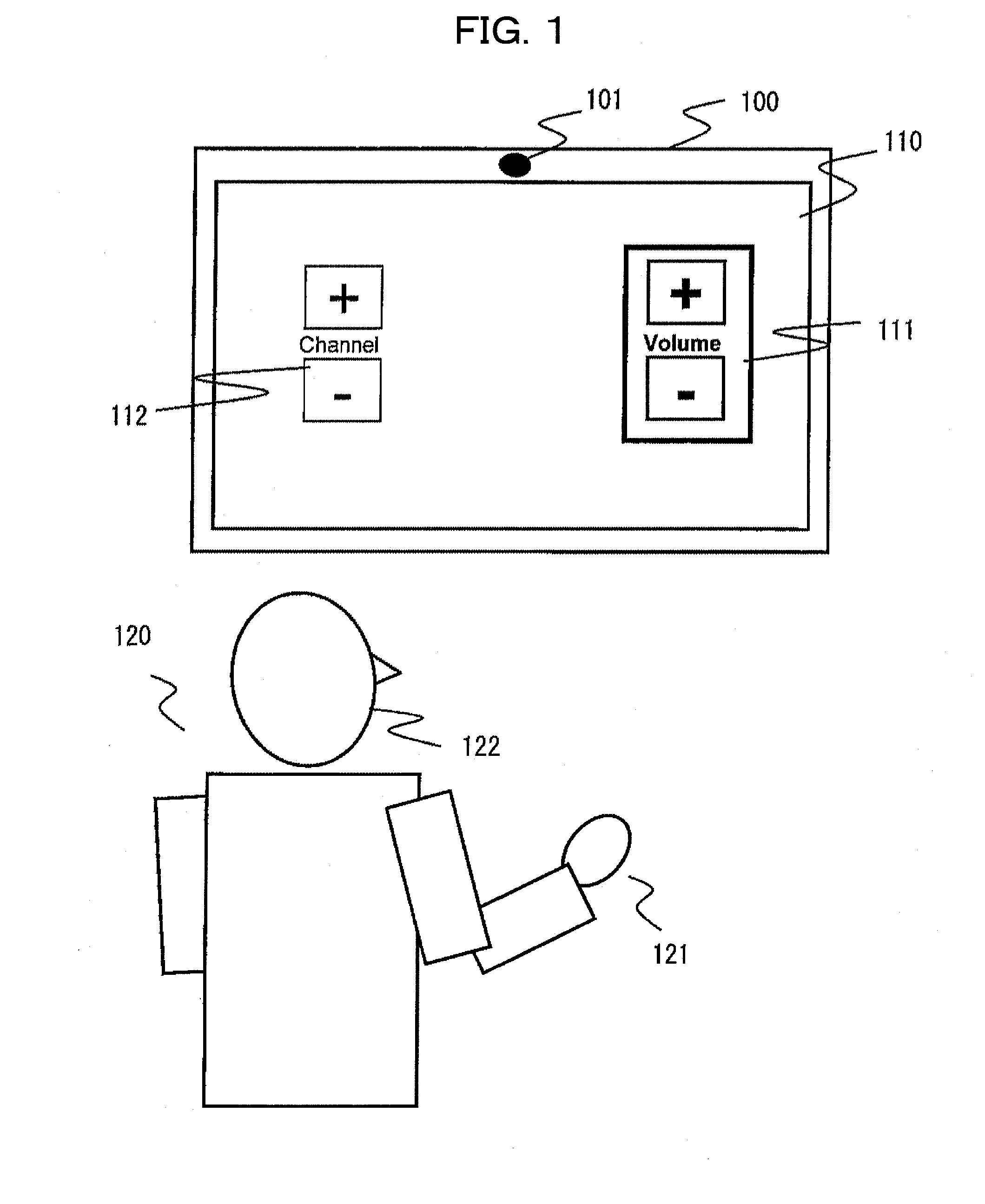
[0028]An input device 100 according to the present embodiment is a device capable of detecting the position of a user's body part from a moving image captured from the user, detecting the user's motion (hereinafter referred to as “gesture”), and according to the detected motion, executing a predetermined processing and also changing the display of the GUI (abbreviation of Graphical User Interface).

[0029]FIG. 1 is a schematic view of an operation environment in which the user operates the input device 100.

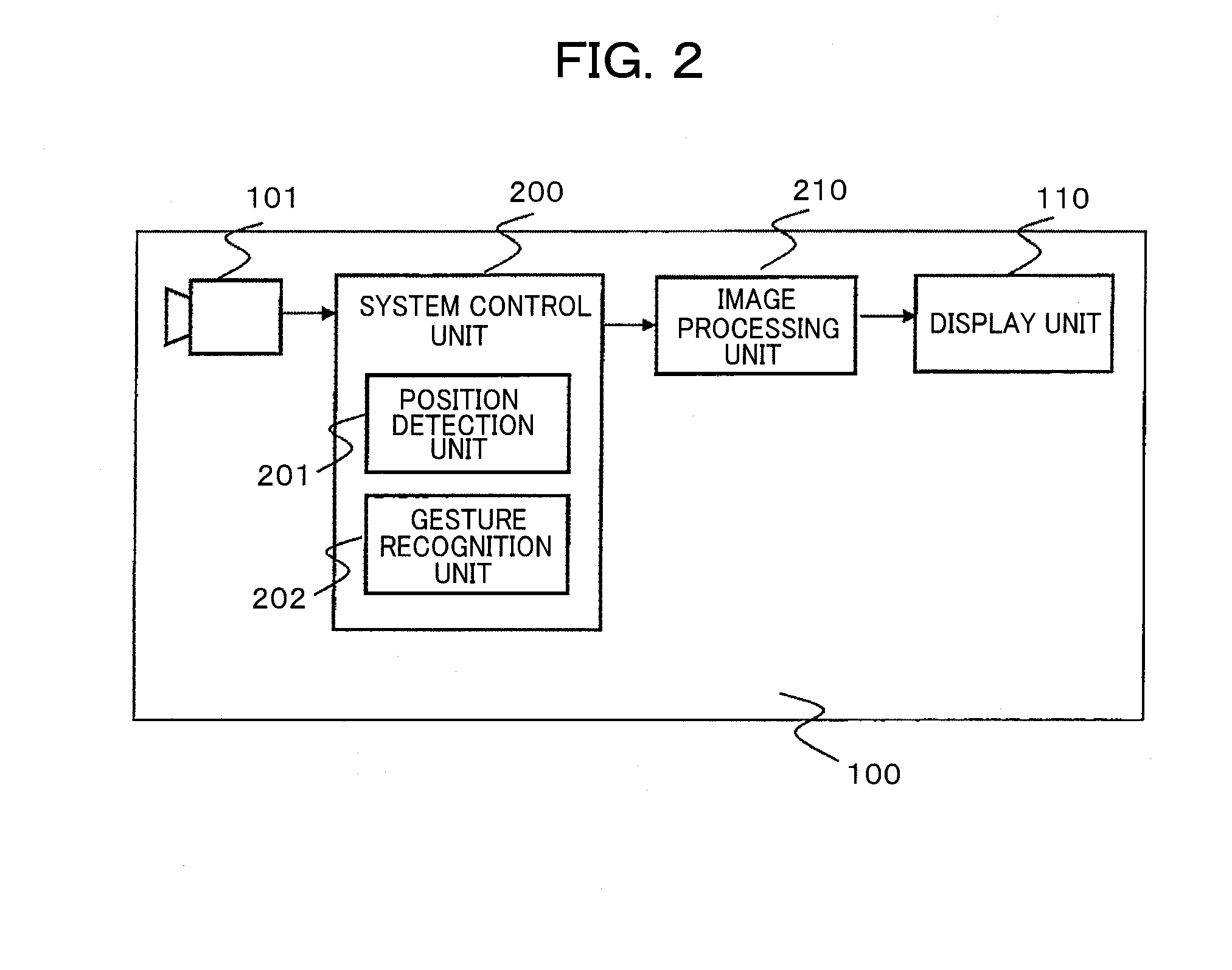
[0030]An imaging unit 101 is a camera for inputting a moving image to the input device 100. A display unit 110 is a display provided in the input device and formed by such a display apparatus as, for example, a liquid crystal display, plasma display, or the like. The display unit 110 includes a display panel, a panel control circuit, and a panel control driver, and displays an image formed by data supplied from an image processing unit 210 which is be described later, to a display p...

second embodiment

[0058]Hereinafter, a second embodiment is described with reference to FIGS. 6 to 8.

[0059]The input device 100 according to the first embodiment displays either a corresponding first or second menu by highlighting when the position of the hand is detected to the right or to the left of the face. In the present embodiment, the GUI displays the position where the user's hand is detected with respect to the face, in addition to the operation method according to the first embodiment.

[0060]FIG. 6 is a schematic view showing the user operating an input device 100. A display unit 110 of the input device 100 is provided with an operation region display 600 indicating the region in which the user's hand is detected, and a GUI of a hand position indicator 601 indicating the position in which the user's hand is detected, in addition to the first menu 111 and the second menu 112 according to the first embodiment. The input device 100 displays the position where the user's hand is detected with r...

third embodiment

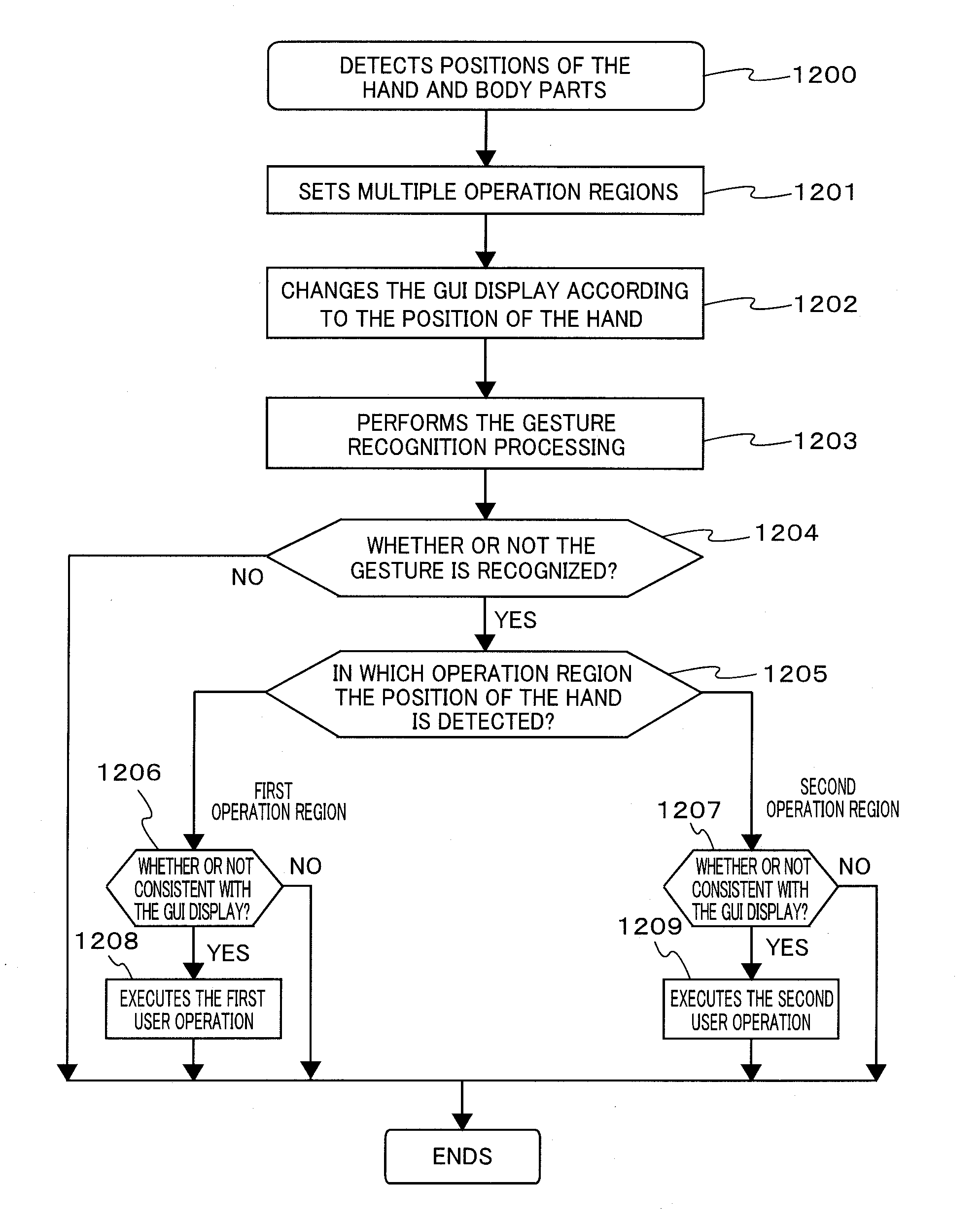
[0064]Hereinafter, a third embodiment is described with reference to FIGS. 9 to 12.

[0065]The input device 100 according to the first and second embodiments is configured so as to set a predetermined reference position by using positional information of the face and allocate a different operation according to the relative position of the hand with respect to the reference position. In this embodiment, a method of allocating operations by the gesture by using a relative position of the user's hand with respect to other body parts is described.

[0066]Firstly, an imaginary boundary line extending longitudinally or laterally, or at a predetermined inclination is created with the user's body parts as a reference. The created imaginary boundary line produces at least two operation regions. In this embodiment, a method of allocating an operation to a predetermined gesture depending on the operation region in which the user's hand is detected is described. Hereinafter, an example of creating ...


PUM


Abstract

The input device and the input system include a hand detection means which detects the position of the hand, a body part detection means which detects positions of user's body parts such as the face, for example, a relative position calculation means which calculates a relative position of the hand with respect to body parts from hand position information being a detection result of the hand detection means and body part position information being a detection result of the body part detection means, and a gesture recognition means which recognizes a hand gesture on the basis of a change in the hand position information being the detection result of the hand detection means, wherein when a hand gesture is recognized, the operation of the input device with respect to the user's gesture is changed according to a relative position of the hand with respect to body parts.

Description

INCORPORATION BY REFERENCE[0001]This application relates to and claims by priority from Japanese Patent Application No. 2010-289122 filed on Dec. 27, 2010, the entire disclosure of which is incorporated herein by reference.BACKGROUND OF THE INVENTION[0002](1) Field of the Invention[0003]The present invention relates to the operation of electronic devices.[0004](2) Description of the Related Art[0005]An invention disclosed by a Japanese Patent Application Laid-Open No. 2003-233452 (hereinafter, referred to as Patent Document 1) is known as a prior art in the field of the present invention. The Patent Document 1 describes that an object of the prior art is “to provide a user-friendly gesture command input device which allows a user to input a command by using a user's favorite gesture irrespective of applications or gesture commands arbitrarily registered by other users and provides an input means which recognizes a specific user performing a gesture input and allows multiple users to...

Claims


Application Information

Patent Timeline
Patent Type & Authority Applications(United States)
IPC IPC(8): H04N7/18G06F3/038
CPCG06F3/017G06F3/011G06F3/005
Inventor SETIAWAN, BONDANMATSUBARA, TAKASHI
Owner MAXELL HLDG LTD
Features
  • Generate Ideas
  • Intellectual Property
  • Life Sciences
  • Materials
  • Tech Scout
  • Unparalleled Data Quality
  • Higher Quality Content
  • 60% Fewer Hallucinations
Learn More