Unlock instant, AI-driven research and patent intelligence for your innovation.

Light Source Device

a light source and light source technology, applied in the field of light source devices, can solve the problems of affecting the color balance of illumination light between r, g, and b, and achieve the effect of good color balan

Inactive Publication Date: 2012-06-28
JVC KENWOOD CORP A CORP OF JAPAN
View PDF11 Cites 45 Cited by
  • Summary
  • Abstract
  • Description
  • Claims
  • Application Information

AI Technical Summary

Benefits of technology

[0009]It is an object of this invention to provide a light source device able to maintain good color balance among R, G, and B of illumination light independently of differences in brightness among excitation light sources and ages thereof.
[0018]In the light source device of the second aspect of this invention, outgoing red, green, and blue light beams are equal in angular distribution. It is possible to maintain good color balance.
[0019]In the light source device of the third aspect of this invention, a high color purity of blue light can be attained.

Problems solved by technology

Thus, differences in brightness among the excitation light sources cause those among the fluorescent layers which impair color balance among R, G, and B of illumination light.

Method used


Image

  • Light Source Device
  • Light Source Device
  • Light Source Device

Examples


first embodiment

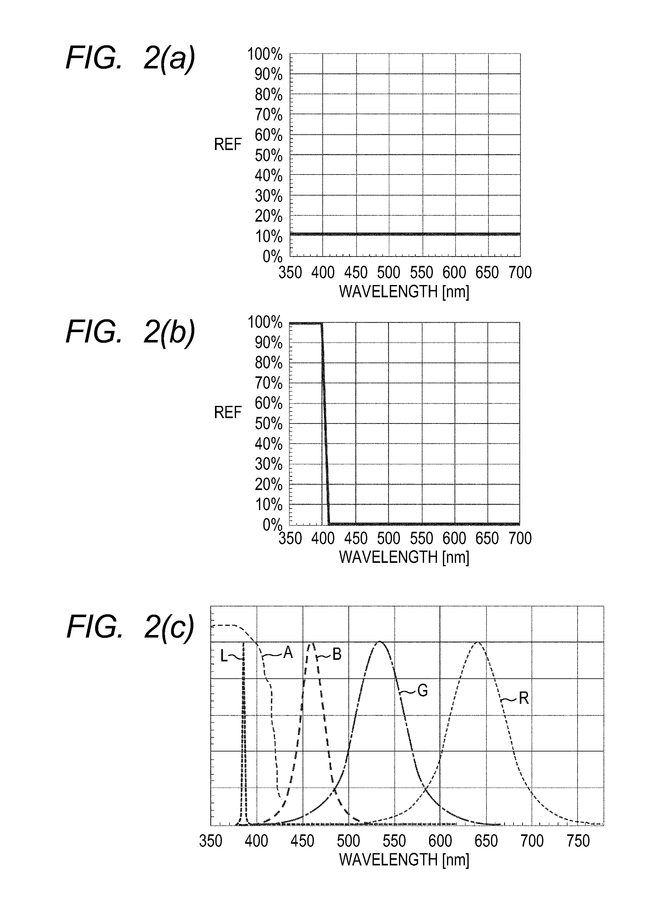
[0049]FIG. 1 shows a light source device according to a first embodiment of this invention. The light source device of FIG. 1 includes an array or arrangement of laser diodes (LDs) 1 mounted on a heat sink la. The LDs 1 emit near-ultraviolet excitation light beams respectively. The emitted excitation light beams have a single wavelength. Preferably, the LDs 1 and the heat sink la are integrated or combined into a module.

[0050]Lenses 1b follow the LDs 1 respectively as viewed in the direction of travel of light. The lenses lb align with the LDs 1 respectively. The lenses 1b receive the excitation light beams from the LDs 1, and convert or collimate them into parallel excitation light beams (collimated excitation light beams) respectively. The lenses 1b, the LDs 1, and the heat sink la may be integrated or combined into a module.

[0051]A first mirror or beam splitter 2 follows the lenses lb as viewed in the direction of travel of light. The first mirror 2 receives the parallel excitati...

second embodiment

[0075]FIG. 5 shows a light source device according to a second embodiment of this invention. The light source device of FIG. 5 includes an array or arrangement of laser diodes (LDs) 1 mounted on a heat sink la. The LDs 1 emit excitation light beams respectively. Each of the emitted excitation light beams has a power of 1.4 W and a wavelength in the range of 430 nm to 460 nm, that is, a blue-range wavelength. The number of the LDs 1 is, for example, 50. Preferably, the LDs 1 and the heat sink la are integrated or combined into a module.

[0076]Lenses lb follow the LDs 1 respectively as viewed in the direction of travel of light. The lenses lb align with the LDs 1 respectively. The lenses lb receive the excitation light beams from the LDs 1, and convert or collimate them into parallel excitation light beams (collimated excitation light beams) respectively. The lenses lb, the LDs 1, and the heat sink la may be integrated or combined into a module.

[0077]Strip-shaped mirrors 11 follow the ...

third embodiment

[0112]A third embodiment of this invention is similar to the second embodiment thereof except for the characteristics of the third mirror 4 and the fourth mirror 6.

[0113]In the third embodiment of this invention, the reflectance M4 of the third mirror 4 depends on the wavelength of incident light as shown in FIG. 9(e). The reflectance M6 of the fourth mirror 6 depends on the wavelength of incident light as shown in FIG. 9(f). The composite light beam exiting the light source device has a spectral energy distribution shown in FIG. 9(g). The reflectances M4 and M6 of the third and fourth mirrors 4 and 6 are designed so that a short-wavelength (blue) portion of the green light beam emitted from the fluorescent member 5g will be used as a part of the blue light beam.

[0114]In the second embodiment of this invention, the blue light in the composite light beam is formed only by a portion of the excitation light having a wavelength centered at 450 nm. Thus, the chromaticity point of the blu...


PUM


Abstract

A light source device includes excitation light sources integrated into a module and each emitting excitation light. A beam splitter optical system splits the excitation light from the excitation light sources into first, second, and third portions. A first fluorescent member emits red light in response to the first portion of the excitation light through fluorescence. A second fluorescent member emits green light in response to the second portion of the excitation light through fluorescence. A third fluorescent member emits blue light in response to the third portion of the excitation light through fluorescence. A combining optical system combines the red light, the green light, and the blue light.

Description

CROSS-REFERENCE TO RELATED APPLICATIONS[0001]This application claims priority from Japanese patent application number 2010-293261, filed on Dec. 28, 2010, the disclosure of which is hereby incorporated by reference.BACKGROUND OF THE INVENTION[0002]1. Field of the Invention[0003]This invention relates to a light source device for illuminating a spatial light modulator or modulators in a projector. This invention also relates to a projector including a light source device.[0004]2. Description of the Related Art[0005]A prior-art projector indicates an image through the use of a spatial light modulator such as a DMD (digital micromirror device). In the prior-art projector, the spatial light modulator is illuminated, and illumination light modulated by the spatial light modulator is projected to indicate the image.[0006]Japanese patent application publication number 2010-086815 discloses a projector including a light source device for illuminating a spatial light modulator. The light sou...

Claims


Application Information

Patent Timeline
IPC IPC(8): G03B21/14F21V9/16
CPCH04N9/3164G03B21/204
Inventor KOBAYASHI, TATSURUMUKOUYAMA, TATSUYATOHDA, MOTOSHI
Owner JVC KENWOOD CORP A CORP OF JAPAN