Cable modem with dual automatic attenuation

a modem and automatic attenuation technology, applied in the field of wireless communication systems and attenuation management, can solve the problems of inability to achieve the effect of attenuation, and inability to prevent signal loss, etc., and achieve the effect of reducing or eliminating

Active Publication Date: 2012-06-28
TELEFON AB LM ERICSSON (PUBL)
View PDF14 Cites 26 Cited by
  • Summary
  • Abstract
  • Description
  • Claims
  • Application Information

AI Technical Summary

Benefits of technology

[0018]The present application aims to reduce or eliminate the above-described unnecessary costs by implementing an algorithm at or near the cable modem to dynamically sense the downstream receiving signal strength and adjusting the attenuation on both the upstream and the downstream links until a desired target signal strength is reached.

Problems solved by technology

As technology progresses and electronic devices become more advanced, one issue that continues to plague system designers is the inevitable signal loss over a span of cable—this power loss is referred to as attenuation.
This is a considerable issue in the cable and telecom industries, which run thousands of miles of cable to provide services to their users.
In the real world, however, this is not the case, and some power is lost along the length of the RF cable, causing less power to reach the user than originally entered the RF cable.
Unfortunately, because lower-loss cable is typically more expensive, cable and telecom companies are reluctant to use it.
Other factors, however, may also impact a cable's attenuation value.
There are a number of causes for the above-described power loss.
A first cause of power loss is radiated loss.
Radiated loss is generally the least important cause because only a miniscule amount of power is generally radiated from most cables.
Nevertheless, very inexpensive coax cables may have a very poor outer braid, and in this case, radiated loss may represent a noticeable element of the loss.
A second cause of loss is resistive loss within the coax cable.
Resistive loss arises from the basic resistance of the conductors (e.g., the copper wire within the cable)—the current flowing in the conductors results in heat being dissipated.
The resistive losses may also increase as the square root of the frequency, meaning that resistive losses normally dominate at lower frequencies.
A third cause of loss is dielectric loss.
The dielectric loss represents a major loss in most coax cables.
As with resistive losses, the power lost as dielectric loss is dissipated as heat.
Therefore, where resistive losses increase as the square root of the frequency, dielectric losses increase linearly, causing the dielectric losses to dominate at higher frequencies.
Furthermore, the cable installers typically over-power each cable strand (a “hot” cable), somewhat, to ensure sufficient signal strength at each tap.
This strategy is problematic because the attenuators must be changed and / or the cable re-coiled every time power changes are propagated through the cable plant.
However, for equipment located directly on the plant, both the levels and the actual operational requirements are different from those of the millions of home cable modems.
However, not yet described, is that these cable modems are required to inject minimal levels of spurious emissions into the plant.

Method used


Image

  • Cable modem with dual automatic attenuation
  • Cable modem with dual automatic attenuation
  • Cable modem with dual automatic attenuation

Examples


Embodiment Construction

[0040]Preferred embodiments of the present invention will be described hereinbelow with reference to the accompanying drawings. In the following description, well-known functions or constructions are not described in detail because they would obscure the invention in unnecessary detail.

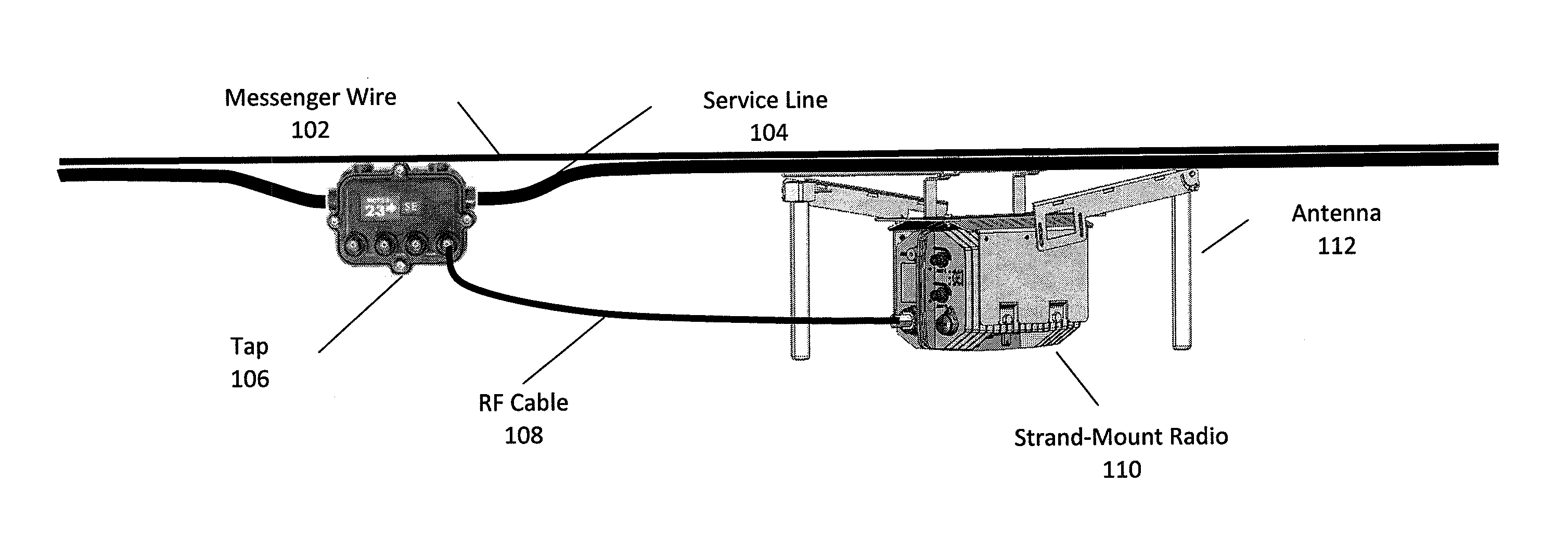
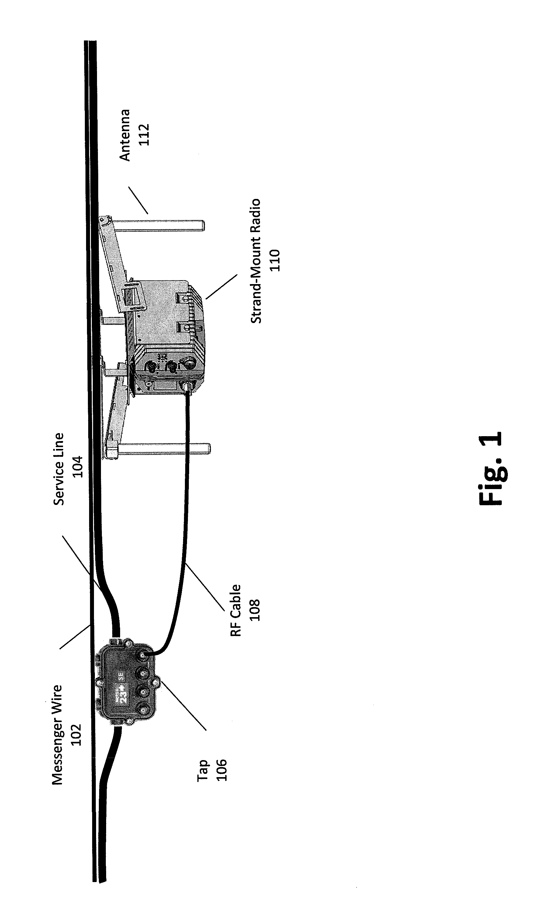
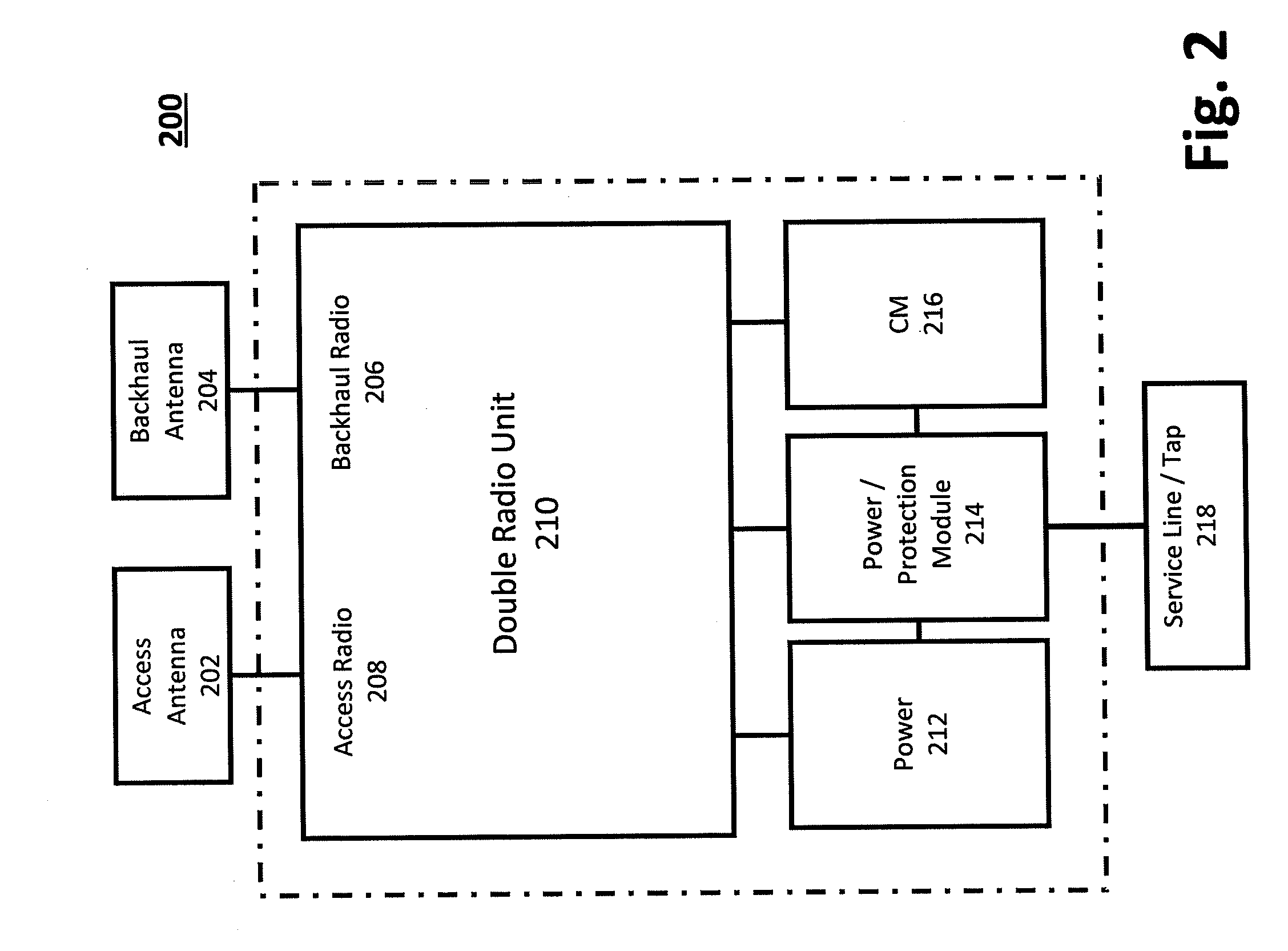
[0041]Described herein are a number of steps, methods, and solutions which may be applied to greatly improve attenuation control of cable-propagating RF signals. The preferred embodiment is directed to a DOCSIS cable modem Auto-Attenuation System (the “Auto-Attenuation System”), but may be applied to any signal transferring system. The Auto-Attenuation System may be capable of taking a high-power signal from the cable plant's service line, dropping the power value down to a usable level, and providing the signal to a cable modem (CM) while eliminating the need for rigorous specifications that a normal cable modem often requires. In certain embodiments, an Auto-Attenuation System may be integrated into...


PUM


Abstract

Described herein are a number of steps, methods and / or solutions that can be applied to greatly improve attenuation control of RF signals in cable plant. The present disclosure is directed to a cable modem auto-attenuation system or any other signal transferring system. The system may be capable of taking a high-power signal from the cable plant's service line, dropping the power value down to a usable level and transmitting the signal to a cable modem while eliminating the need for rigorous manual adjustments that a normal cable modem often requires. In certain embodiments, the system may be integrated into a separate device connected between the modem and the cable company service line and configured to handle upstream and downstream attenuation separately or jointly.

Description

TECHNICAL FIELD[0001]The present disclosure relates to wireless communication systems and attenuation management. More specifically, the present invention relates to enhancements protocols and algorithms for automatic control of cable modem attenuation.BACKGROUND[0002]As technology progresses and electronic devices become more advanced, one issue that continues to plague system designers is the inevitable signal loss over a span of cable—this power loss is referred to as attenuation. Attenuation is a key specification for all cables (e.g., coaxial cable, a type of cable that supplies a signal to a cable modem) and affects the propagation of signals in upstream and downstream electrical circuits. This is a considerable issue in the cable and telecom industries, which run thousands of miles of cable to provide services to their users. The basic function of a coax cable is to act as a pipe, transferring RF (radio frequency) signals from a signal source to a receiver (e.g., from the cab...

Claims


Application Information

Patent Timeline
Patent Type & Authority Applications(United States)
IPC IPC(8): H04L12/26H04B1/44
CPCH04N7/102H04L43/00H04L12/2801
Inventor WILLIAMS, CHRISSMITH, ROLANDZANIEWSKI, JAREKCHENIER, MARCELRAYMENT, STEPHEN
Owner TELEFON AB LM ERICSSON (PUBL)
Why Eureka
Try Eureka