In-plane capacitive MEMS accelerometer

a capacitive accelerometer and in-plane technology, applied in the direction of speed/acceleration/shock measurement, measurement devices, instruments, etc., can solve the problem of changing the area of the gap between the upper surface of each substra

Active Publication Date: 2012-07-05
ROSEMOUNT AEROSPACE
View PDF4 Cites 14 Cited by
  • Summary
  • Abstract
  • Description
  • Claims
  • Application Information

AI Technical Summary

Problems solved by technology

This results in a change in the area of the gap between the upper surface of each of the substrate electrodes and the proof mass.

Method used


Image

  • In-plane capacitive MEMS accelerometer
  • In-plane capacitive MEMS accelerometer
  • In-plane capacitive MEMS accelerometer

Examples


Embodiment Construction

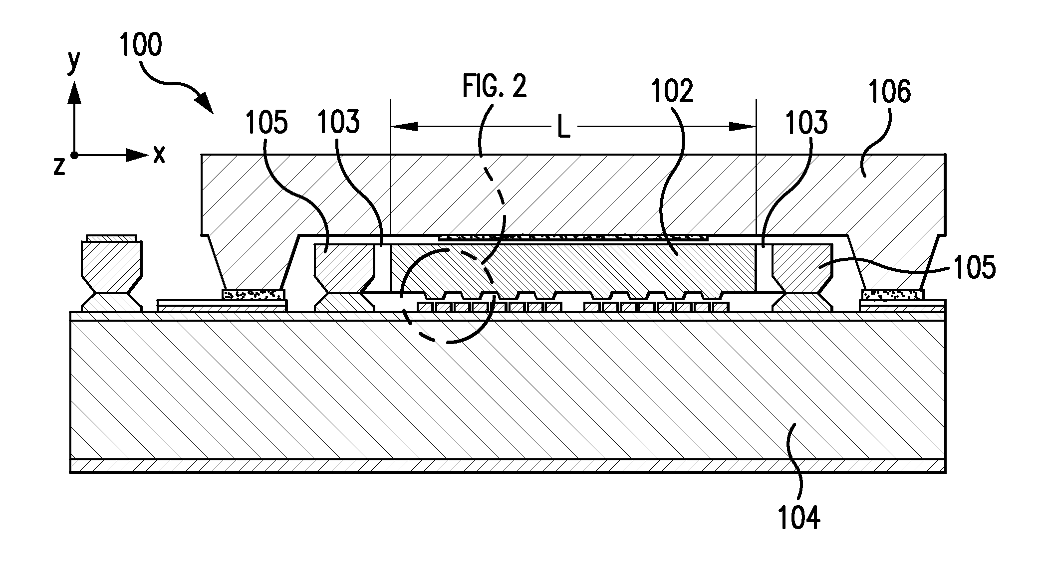
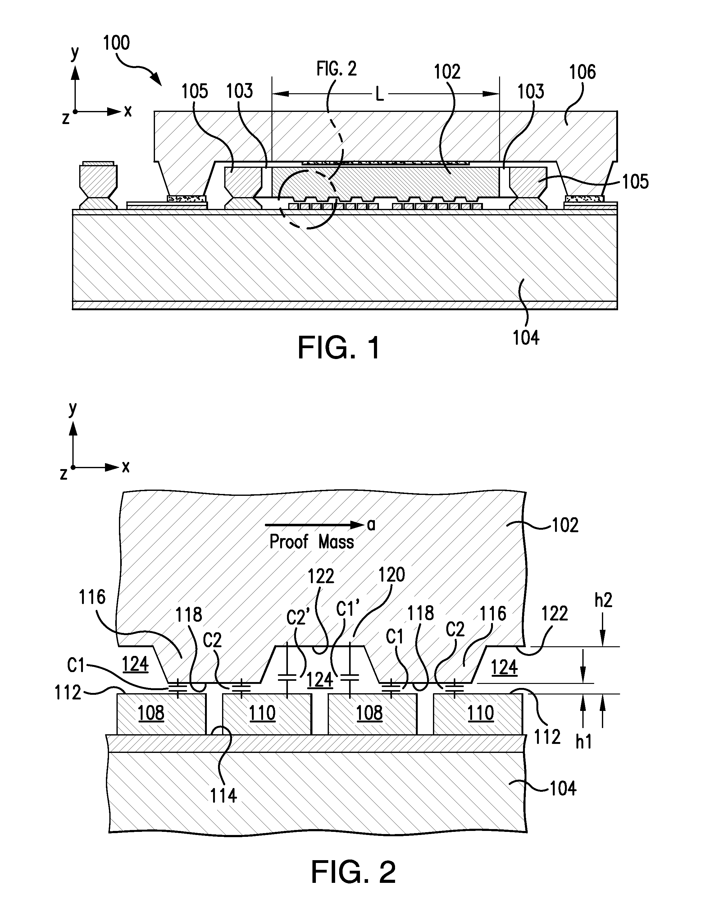
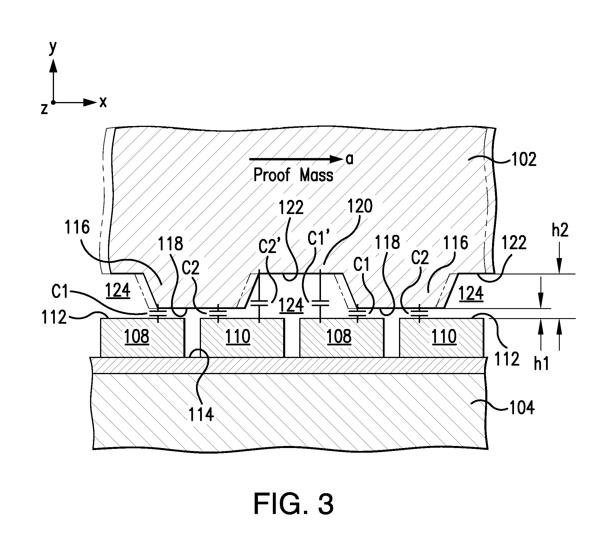
[0024]There is a compelling need for a gun-hard, high-performance, three-axis inertial measurement unit that includes both in-plane accelerometers and out-of-plane accelerometers on a single chip. A novel out-of-plane MEMS accelerometer suitable for this purpose is described in U.S. patent application Ser. No. 11 / 978,090, filed Oct. 26, 2007, and titled “Pendulous Accelerometer with Balanced Gas Damping.” That application, which is incorporated herein by reference, describes a pendulous capacitive accelerometer with an asymmetric proof mass. The pendulous sensing plate includes a first side that is substantially hollow and a second side that is solid. The out-of-plane accelerometer described in that application uses a 75 μm (micron) silicon-on-insulator (SOI) layer as a sensing structure. Such asymmetric solid / hollow proof mass sensor structures exhibit higher sensitivity than surface micromachined rocking structures because of the relatively thick proof mass and narrow vertical gap...


PUM


Abstract

A system for determining in-plane acceleration of an object. The system includes an in-plane accelerometer with a substrate rigidly attached to an object, and a proof mass—formed from a single piece of material—movably positioned a predetermined distance above the substrate. The proof mass includes a plurality of electrode protrusions extending downward from the proof mass to form a gap of varying height between the proof mass and the substrate. The proof mass is configured to move in a direction parallel to the upper surfaces of each of the plurality of substrate electrodes when the object is accelerating, which results in a change in the area of the gap, and a change in capacitance between the substrate and the proof mass. The in-plane accelerometer can be fabricated using the same techniques used to fabricate an out-of-plane accelerometer and is suitable for high-shock applications.

Description

BACKGROUND OF THE INVENTION[0001]1. Field of the Invention[0002]The present invention relates to accelerometers and other force-sensing devices, and more particularly to a gun-hard, in-plane MEMS capacitive accelerometer that includes a proof mass formed from a single piece of material positioned above a plurality of electrodes on a substrate. When the substrate accelerates, the proof mass moves in a direction parallel to the upper surfaces of the substrate, changing the capacitance between the proof mass and the substrate. This change in capacitance can be used to measure the displacement and to determine the acceleration of an object to which the substrate is attached.[0003]2. Description of Related Art[0004]Accelerometers are a critical component in the Inertial Measurement Units (IMUs) commonly used in navigation and guidance systems for all types of vehicles. A typical IMU consists of three equal modules, each including a linear accelerometer, a gyroscopic rotational rate senso...

Claims


Application Information

Patent Timeline
Patent Type & Authority Applications(United States)
IPC IPC(8): G01P15/125
CPCG01P15/125G01P15/0802G01P2015/0814
Inventor GUO, SHUWENSPIVAK, ALEXANDERFINK, ANITA
Owner ROSEMOUNT AEROSPACE
Why Eureka
Try Eureka