Integrated Illumination Assembly for Symbology Reader

a symbology reader and integrated technology, applied in the field of illumination, can solve the problems of inability to intuitively choose bright field, dark field, direct or diffuse light, and use of highly reflective bright field illumination, so as to improve illumination performance, increase the durability of light pipes, and increase the effect of weight or siz

Active Publication Date: 2012-07-05
COGNEX TECH & INVESTMENT
View PDF0 Cites 66 Cited by
  • Summary
  • Abstract
  • Description
  • Claims
  • Application Information

AI Technical Summary

Benefits of technology

[0019]This invention overcomes the disadvantages of the prior art by providing a plurality of novel features that can be applied variously to a reader to improve the illumination performance in both dark field/direct bright field and direct diffuse types of illu

Problems solved by technology

Conversely, where a symbology or other subject is formed on a more-irregular surface, or is created by etching or peening a pattern directly on the surface, the use of highly reflective bright field illumination may be inappropriate.
A peened/etched surface has two-dimensional properties that tend to scatter bright field illumination, thereby obscuring the acquired image.
Often, the choice of bright field, dark field, direct or diffuse light is not intuitive to user for many types of surfaces and/or the particular angles at which the reader is directed toward them.
However, acrylic tends to shatter easily in response to impact.
This may limit the life and endurance of a handheld reader (particularly a cordless/wireless model) that is expected to occasionally drop and strike a hard floor, perhaps against the light pipe.
While the light pipe c

Method used


Image

  • Integrated Illumination Assembly for Symbology Reader
  • Integrated Illumination Assembly for Symbology Reader
  • Integrated Illumination Assembly for Symbology Reader

Examples


Embodiment Construction

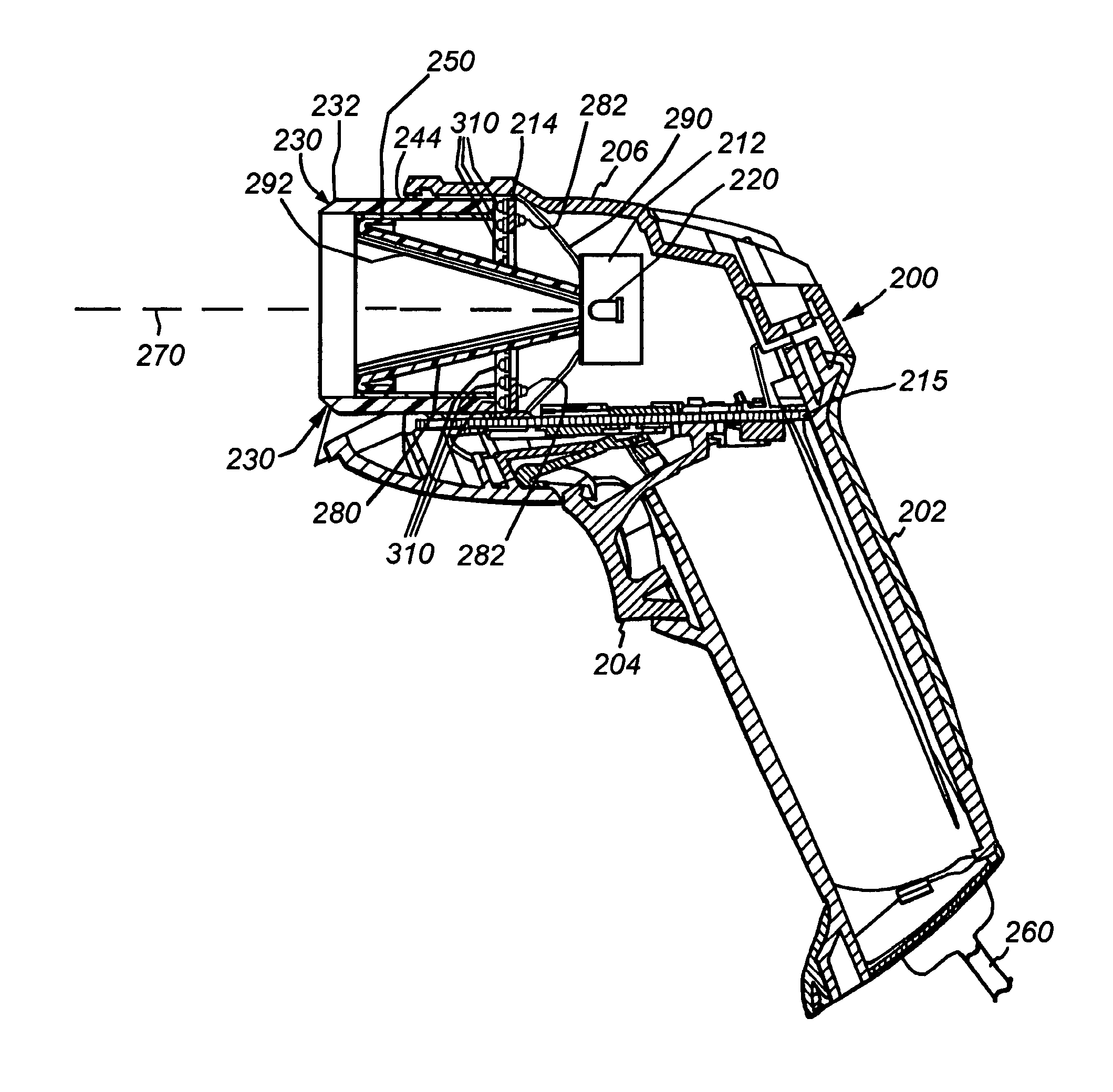
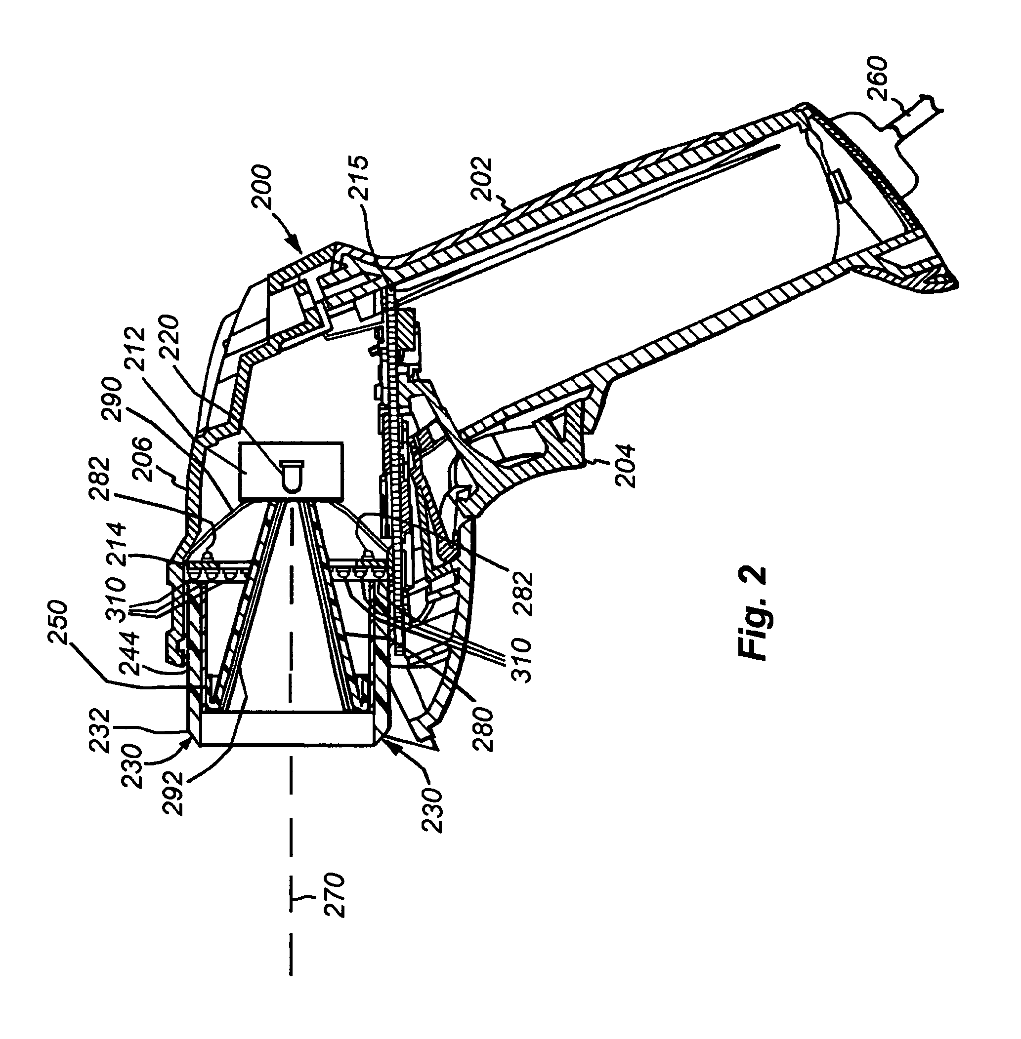
[0053]FIG. 2 shows a cross sectional side view of an illustrative embodiment of the reader 200 according to the present invention. The imager 212 and an illumination board 214 are positioned on a shock-resistant mounting (not shown) within the housing 206. In this exemplary embodiment, the processor module and related functional electronic components are mounted on a processor board 215. The grip portion 202 and the trigger 204 are functionally cooperative with the housing 206 and components of the processor board 215. The grip portion 206 includes a conveniently placed trigger 204 that can be actuated by a finger of the user to initiate the image acquisition and decoding function. More particularly, pressing the trigger causes all types and colors of illumination (as described further below) to be simultaneously projected onto the subject of interest, and also causes corresponding acquisition of an image by the imager.

[0054]With brief reference to the illuminator, the illumination ...


PUM


Abstract

Systems and methods provide an illumination assembly for a mark reader. A light transmitter is arranged in a surrounding relationship to an interior area, with the light transmitter having a proximal end and a distal end. An illumination source provides a light for transmission into the light transmitter. The light transmitter distal end allows the light from within the light transmitter to pass through and out of the distal end to provide bright field illumination and dark field illumination. The light transmitter distal end may include a first portion and a second portion, where light from within the light transmitter passes through and out of the first portion to provide bright field illumination, and light from within the light transmitter passes through and out of the second portion to provide dark field illumination.

Description

CROSS-REFERENCE TO RELATED APPLICATIONS[0001]This application is a continuation-in-part of U.S. patent application Ser. No. 13 / 294,286, filed Nov. 11, 2011, and entitled “Light Pipe Illumination System and Method,” which is a continuation of U.S. patent application Ser. No. 12 / 900,593 filed Oct. 8, 2010, now U.S. Pat. No. 8,061,614 dated Nov. 22, 2011, and entitled “Light Pipe Illumination System and Method,” which is a continuation of U.S. patent application Ser. No. 10 / 693,626 filed Oct. 24, 2003, now U.S. Pat. No. 7,823,783 dated Nov. 2, 2010, and also entitled “Light Pipe Illumination System and Method,” both of which are hereby incorporated by reference.[0002]This application is also a continuation-in-part of U.S. patent application Ser. No. 12 / 900,605 filed Oct. 8, 2010, and entitled “Low Profile Illumination for Direct Part Mark Reader,” which is a continuation of U.S. patent application Ser. No. 11 / 019,763 filed Dec. 21, 2004, now U.S. Pat. No. 7,823,789 dated Nov. 2, 2010, ...

Claims


Application Information

Patent Timeline
IPC IPC(8): G06K7/14
CPCG06K7/10732H04N1/107G06K2207/1011
Inventor NUNNINK, LAURENSEQUITZ, WILLIAM H.
Owner COGNEX TECH & INVESTMENT
Why Eureka
Try Eureka