
Occupancy sensor with multi-level signaling

a multi-level signaling and occupancy sensor technology, applied in the field of occupancy sensor with multi-level signaling, can solve the problems of achieve the effects of simple, limited energy management capability, and simple basic energy managemen

Active Publication Date: 2012-07-05
SCHNEIDER ELECTRIC USA INC
View PDF3 Cites 31 Cited by
  • Summary
  • Abstract
  • Description
  • Claims
  • Application Information

AI Technical Summary

Benefits of technology

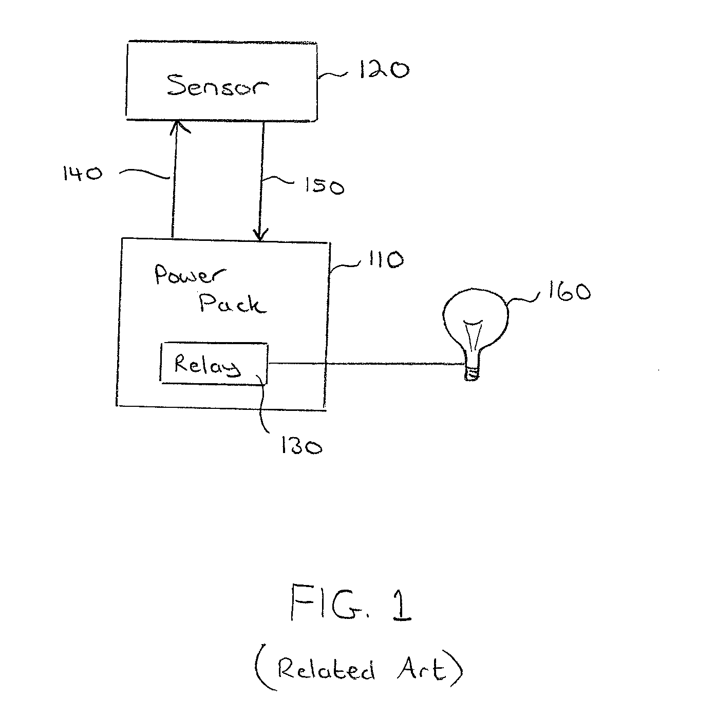
[0007]The conventional occupancy sensor and power pack combination discussed above with reference to FIG. 1 provides a simple, basic level of energy management of lighting loads; however, the energy management capability is limited, in particular due to the singular purpose of the occupancy signal line 150 and limited functionality of the power pack 110. Therefore, a need exists for a power pack and occupancy sensor combination that can provide a higher level of energy management, while preferably also being easy to use, simple to install, and cost effective.
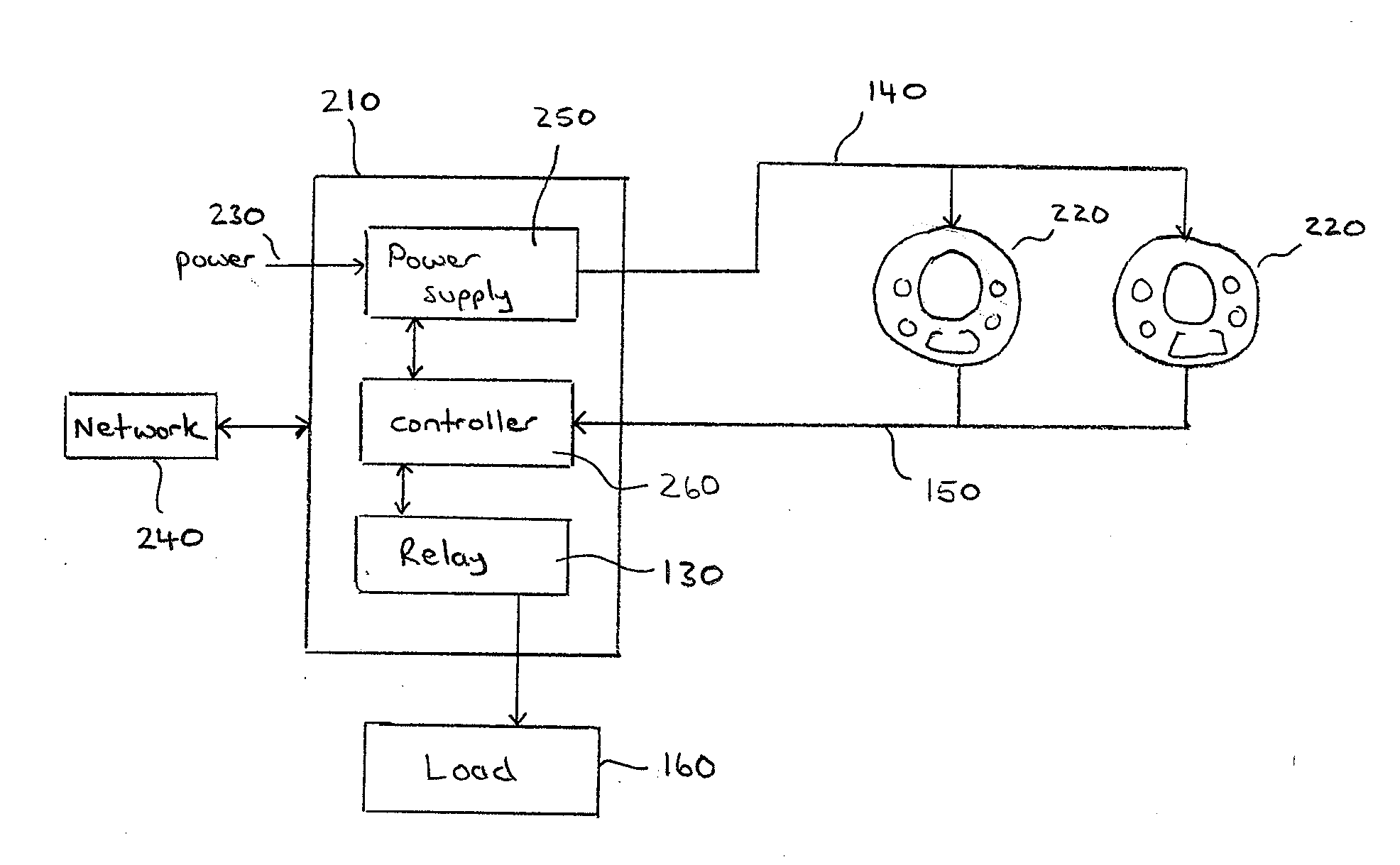
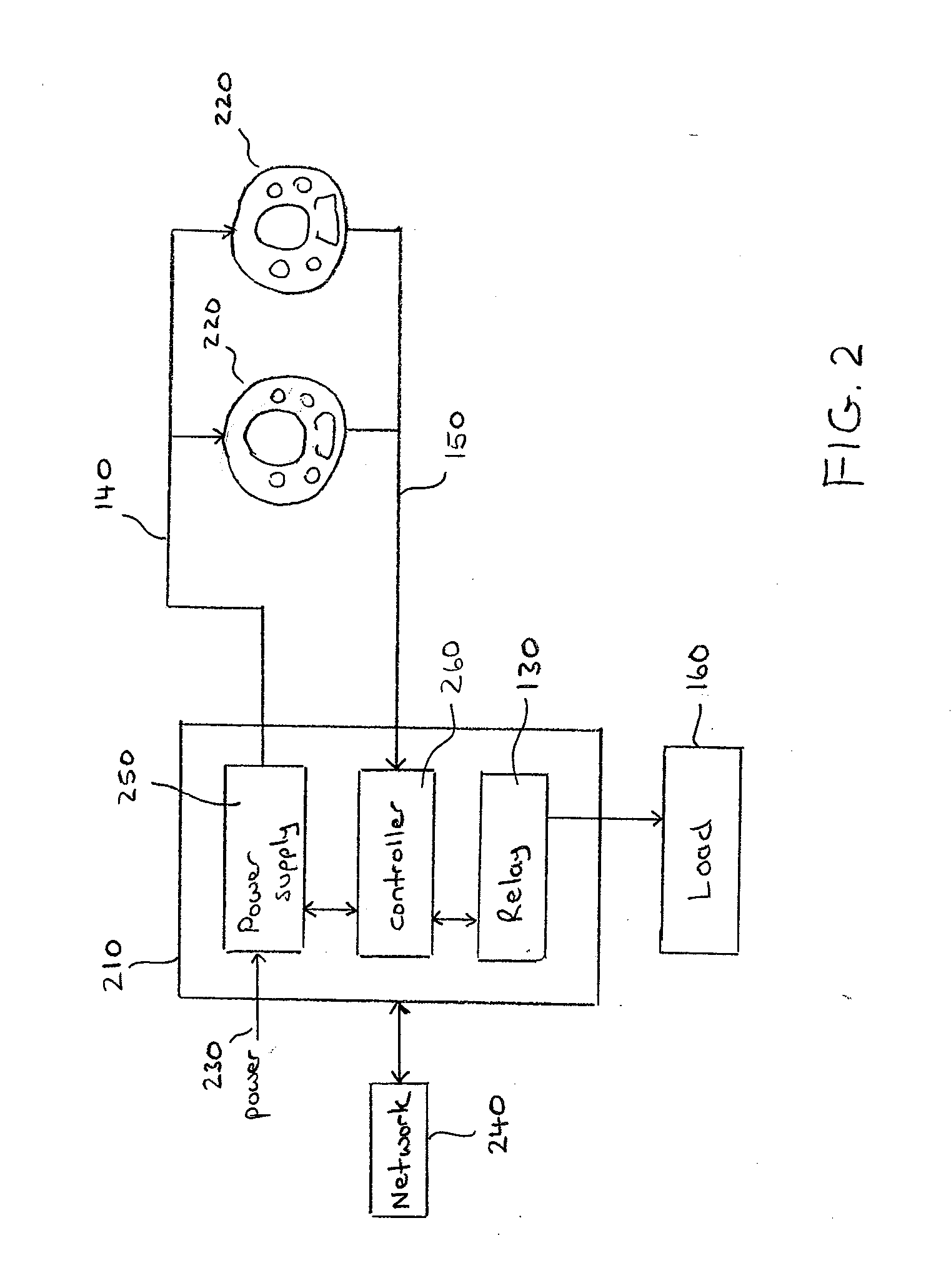
[0008]Accordingly, aspects and embodiments of the present invention are directed to a lighting control system which includes an occupancy sensor configured for multi-level signaling, and a power pack configured to listen for and interpret the multi-level signaling, allowing for more sophisticated and / or accurate lighting control and energy management capability. In one embodiment, the occupancy sensor provides additional information, such as information regarding movement detected in the monitored area, encoded into an occupancy signal, and thus provides a tri-level signal conveying both occupancy and movement information. A specialty power pack according to embodiments of the present invention is configured to detect and respond to the encoded information, thereby providing enhanced functionality to the lighting control system, as discussed further below. In addition, embodiments of a lighting control system are configured to accommodate a manual override switch to allow an occupant to control lighting within an area. Multi-level signaling is further used to provide override commands from the manual override switch to the power pack on the same signal line used for occupancy, thereby avoiding the need for the power pack to have a separate signal port or additional wiring, as discussed further below.

Problems solved by technology

The conventional occupancy sensor and power pack combination discussed above with reference to FIG. 1 provides a simple, basic level of energy management of lighting loads; however, the energy management capability is limited, in particular due to the singular purpose of the occupancy signal line 150 and limited functionality of the power pack 110.

Method used


Image

  • Occupancy sensor with multi-level signaling
  • Occupancy sensor with multi-level signaling
  • Occupancy sensor with multi-level signaling

Examples


Embodiment Construction

[0030]The occupancy sensor and power pack combination discussed above with reference to FIG. 1 provides a simple and effective solution to energy savings; however, the solution is limited due to the singular purpose of the signal line 140 and limited functionality of the power pack 110. Commonly-owned related U.S. patent applications Ser. No. 12 / 645,626 titled “Networked Occupancy Sensor and Power Pack” filed Dec. 23, 2009, and Ser. No. 12 / 645,674 titled “Occupancy Sensor With Embedded Signaling Capability” filed Dec. 23, 2009 describe a method of inserting additional information into the stationary output of the occupancy sensor to enhance the functionality of the lighting control system. The occupancy sensor generally signals the power pack with a constant or steady DC voltage (for example +24 Vdc) signal initiated by an instance of movement; hence the term “stationary output” refers to this generally constant signal. A +24 Vdc level on the signal line 150 instructs the power pack...


PUM


Abstract

A lighting control system includes a power pack and an enhanced occupancy sensor configured to implement multi-valued signaling to encode additional information into the occupancy signal it provides on the signal line. The power pack is configured to monitor the signal line to detect and interpret the additional information. In one example, the lighting control system also includes a manual override switch coupled to the signal line and / or to the occupancy sensor.

Description

BACKGROUND[0001]1. Field of the Invention[0002]The present invention relates generally to lighting control systems and, more particularly, to lighting control systems using zones with multiple occupancy sensors.[0003]2. Discussion of Related Art[0004]Lighting control systems employ sensors and controllers to automatically and selectively power light fixtures on and off, thereby providing light where and when it is needed and reducing lighting in unoccupied areas to achieve energy and cost savings. Many lighting control systems employ occupancy sensors to conserve energy by activating and deactivating light fixtures automatically, depending upon occupancy of areas. Occupancy sensors typically provide a stationary signal (i.e., constant voltage or current level for a predetermined time period) representing occupancy, which is derived from an occurrence of movement. Since an occupant is generally not continuously in motion, a time delay is added to an occurrence of movement to create a...

Claims


Application Information

Patent Timeline
IPC IPC(8): H05B37/02
CPCH05B37/0227H05B47/115Y02B20/40
Inventor OLSON, JAMES V.
Owner SCHNEIDER ELECTRIC USA INC
Learn More