
Touch panel and display device provided with the same

a display device and touch panel technology, applied in the field of touch panel, can solve the problems of reducing the transmissivity of the touch panel, increasing the cost, and difficult to see the display image, and achieve the effect of preventing the pattern of touch electrodes from being visible to a user

Inactive Publication Date: 2012-07-05
SHARP KK
View PDF4 Cites 32 Cited by
  • Summary
  • Abstract
  • Description
  • Claims
  • Application Information

AI Technical Summary

Benefits of technology

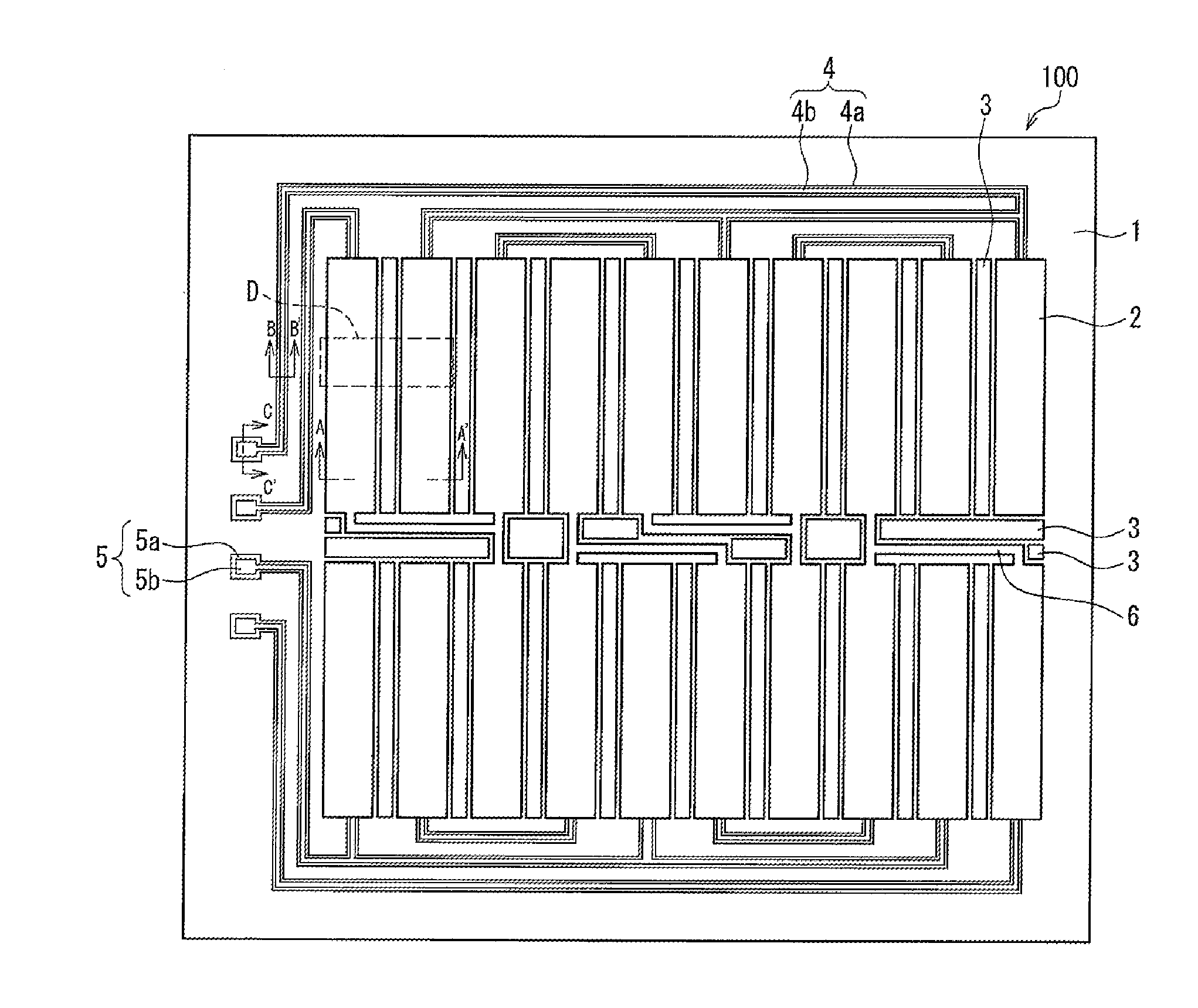
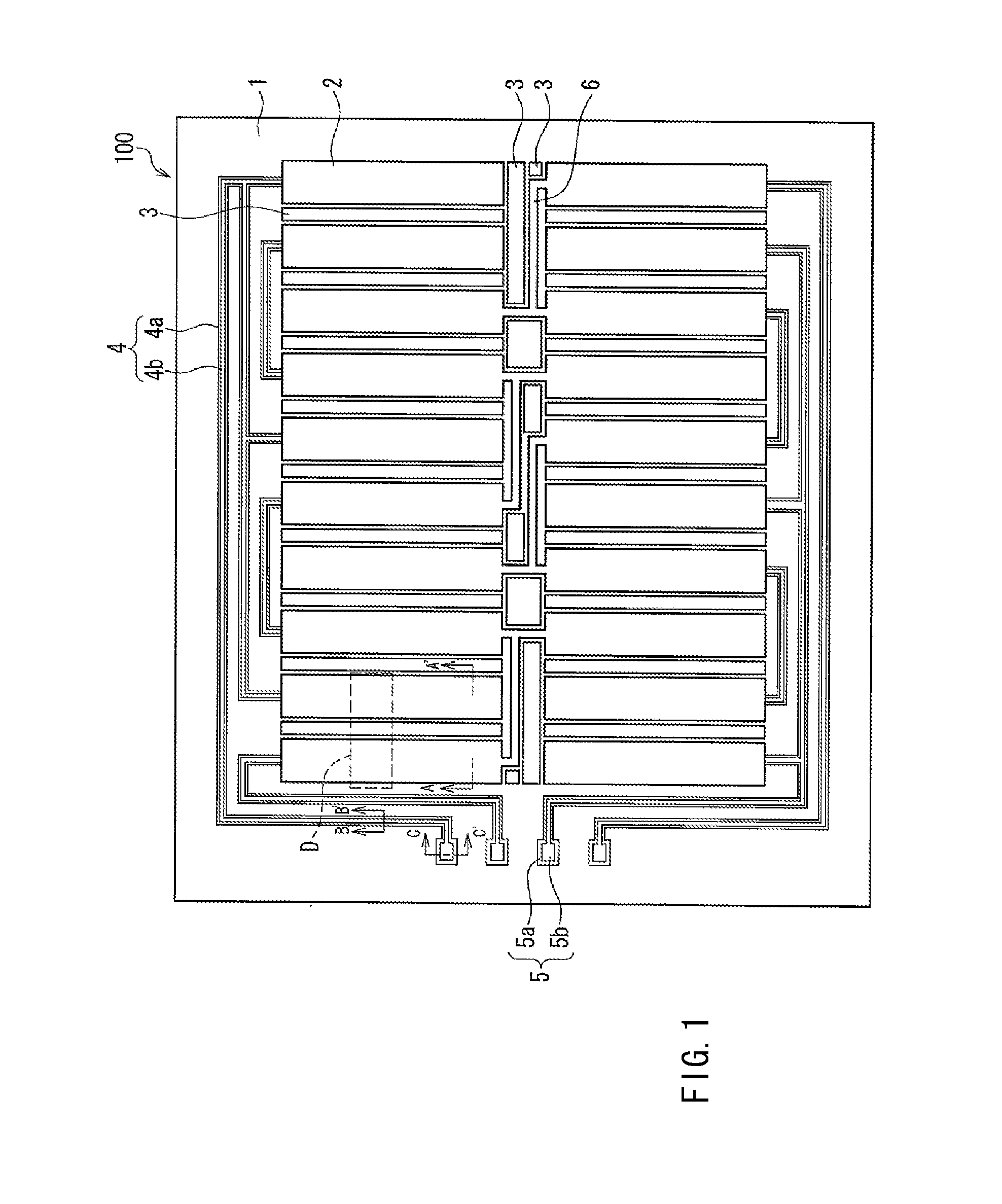
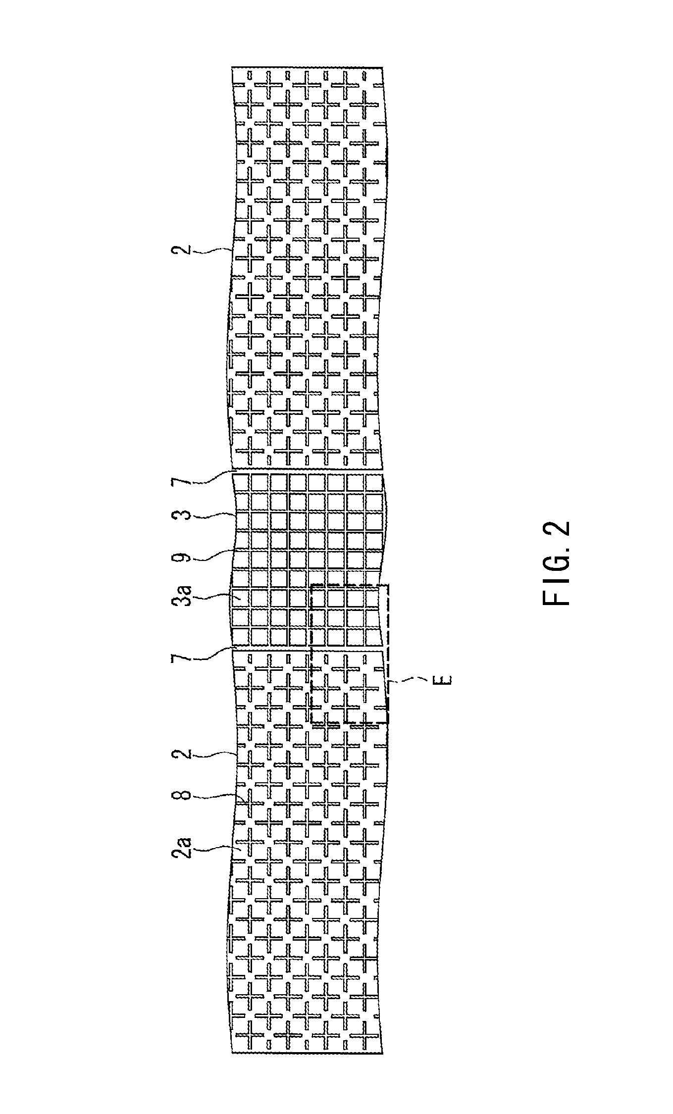
The present invention provides a touch panel with a simple configuration that prevents the pattern of touch electrodes from being visible to a user. This is achieved by forming touch electrodes and a floating electrode on a transparent substrate, with the touch electrodes having slits to create microareas. This results in a more cost-effective manufacturing process and maintains the transparency of the touch panel for easy viewing of display images.

Problems solved by technology

In the case of the touch panel in which the conventional film material is used, however, one or more layers of undercoat are applied to the transparent substrate, which needs more steps in the manufacturing process, leading to an increase in the costs.
Further, in the case where the above-described undercoat layers are formed on a display device, the transmissivity of the touch panel decreases, which makes a display image difficult to see.

Method used


Image

  • Touch panel and display device provided with the same
  • Touch panel and display device provided with the same
  • Touch panel and display device provided with the same

Examples


embodiment

[0034]Hereinafter, an embodiment of the present invention is explained with reference to the drawings.

[0035]It should be noted that in the following description of the embodiment explains, as an example of a touch panel, a projection-type electrostatic capacitance touch panel for a liquid crystal display device, in which a front substrate of a liquid crystal panel is used as a substrate for the touch panel.

[0036]The following explanation, however, does not limit the configurations and use applications of the touch panel and the touch-panel-equipped display device. A touch panel according to one embodiment of the present invention is not limited to a projection-type electrostatic capacitance touch panel, but the present invention can be applied to various touch panels as long as two-dimensionally patterned transparent conductive films are used as touch electrodes. For example, the present invention can be applied to a two-layer touch panel in which touch electrodes are arrayed in X a...


PUM


Abstract

Provided is a touch panel wherein, by a simple configuration, touch electrodes formed on a transparent insulating substrate can be prevented from being visible. A touch panel (100) includes a transparent substrate (1) having an insulating property; a touch electrode (2) formed of a transparent conductive film formed in a pattern on the substrate (1); and a floating electrode (3) formed of a transparent conductive film, the floating electrode (3) being formed in an area on the substrate (1) where the touch electrode (2) is not formed. The touch electrode (2) and the floating electrode (3) respectively have slits (8, 9) so that a plurality of microareas (2a, 3a) are formed in the same.

Description

REFERENCE TO RELATED APPLICATIONS[0001]This application is the national stage under 35 USC 371 of International Application No. PCT / JP2010 / 064295, filed Aug. 10, 2010, which claims priority from Japanese Patent Application No. 2009-213098, filed Sep. 15, 2009, the entire contents of which are incorporated herein by reference.FIELD OF THE INVENTION[0002]The present invention relates to a touch panel having touch electrodes formed with transparent conductive films on a transparent insulating substrate, and to a display device provided with this touch panel.BACKGROUND OF THE INVENTION[0003]Recently, with the spread of personal digital assistants (PDA), palm top computers, portable game equipment, etc., a touch panel formed on a transparent substrate has been known widely as an input means that can be combined with a display device.[0004]For example, in a liquid crystal display device as a touch-panel-equipped display device, a transparent touch panel is laminated on an image display su...

Claims


Application Information

Patent Timeline
Patent Type & Authority Applications(United States)
IPC IPC(8): G06F3/044
CPCG06F2203/04112G06F3/044G06F3/0412G06F3/04164G06F3/0443G06F3/0448
Inventor MISAKI, KATSUNORI
Owner SHARP KK
Learn More