Measuring method for topography of moving specimen and a measuring apparatus thereof

a moving specimen and topography technology, applied in the direction of measuring devices, instruments, optical means, etc., can solve the problems of inability to acquire sufficient luminous intensity signals, inability to produce a lot of defective products, and inability of measuring apparatuses to acquire complete position signals, etc., to achieve the effect of reducing the relative velocity between a fast moving specimen and a measuring modul

Active Publication Date: 2012-07-05
IND TECH RES INST
View PDF13 Cites 6 Cited by
  • Summary
  • Abstract
  • Description
  • Claims
  • Application Information

AI Technical Summary

Benefits of technology

[0009]The present disclosure is to provide a method and apparatus for measuring the topography of moving specimens, operationally that the relative velocity between a fast moving specimen and a measuring module is reduced for enabling the measuring module to acquire sufficient luminous intensity signal at the same position in time trying to avoid being adversely affected by ambient environment or other irresistible factors, and thereby, to measure the topography or the thickness of the testing specimen based upon optical measurement principles including chromatic confocal principle and / or laser triangulation principle.

Problems solved by technology

However, in those rapid mass production processes, it is possible to have a plenty of defective products being produced if a decision can not be made immediately for shutting down the production processes in the case of an abnormality.
On the other hand, for DUTs with low surface reflectivity, it may unable to obtain the required lateral resolution simply by increasing the sampling frequency of the measuring apparatus, since the increasing of sampling frequency may cause the exposure of each and every location of signal acquisition to be not sufficient, resulting that the measuring apparatus may unable to acquire complete location signals.
Accordingly, while performing an optical measurement in a rapid continuous manufacturing process where the products to be measured are being transported at high speed, it is likely that the optical measurement will not be able to acquire sufficient luminous intensity signal at the same position in time when the products are objects with low reflectivity, such as optical films.
Thus, the stationary optical measuring apparatuses may incapable of being used to acquire sufficient luminous intensity signal at the same position in time for products that are being transported at high speed.
On the other hand, although some optical measuring apparatuses are designed to be movable, they are restricted for measuring products that are stationary and thus may not be used for measuring products that are being transported at high speed.

Method used


Image

  • Measuring method for topography of moving specimen and a measuring apparatus thereof
  • Measuring method for topography of moving specimen and a measuring apparatus thereof
  • Measuring method for topography of moving specimen and a measuring apparatus thereof

Examples


Embodiment Construction

[0029]For your esteemed members of reviewing committee to further understand and recognize the fulfilled functions and structural characteristics of the disclosure, several exemplary embodiments cooperating with detailed description are presented as the follows.

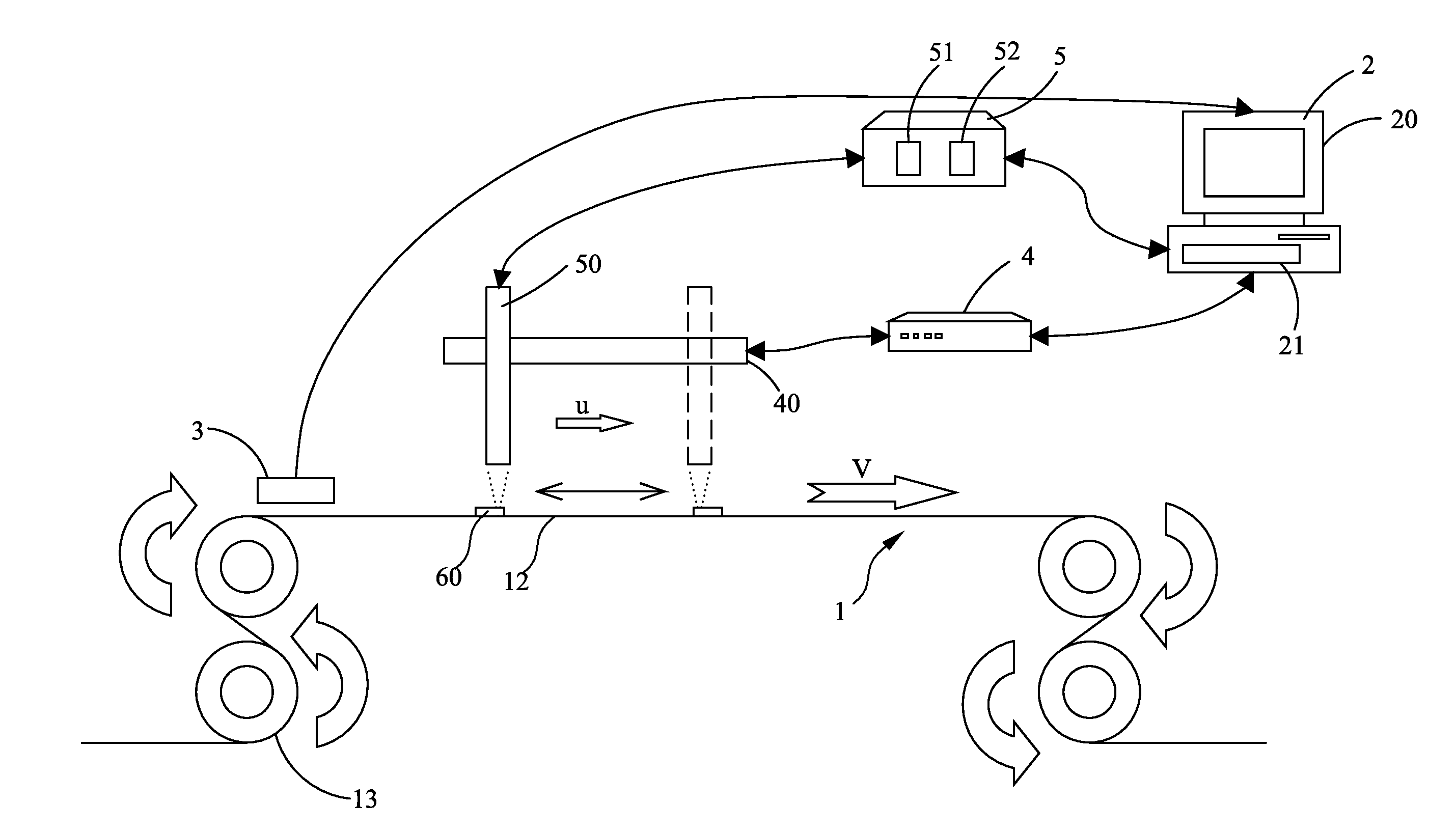
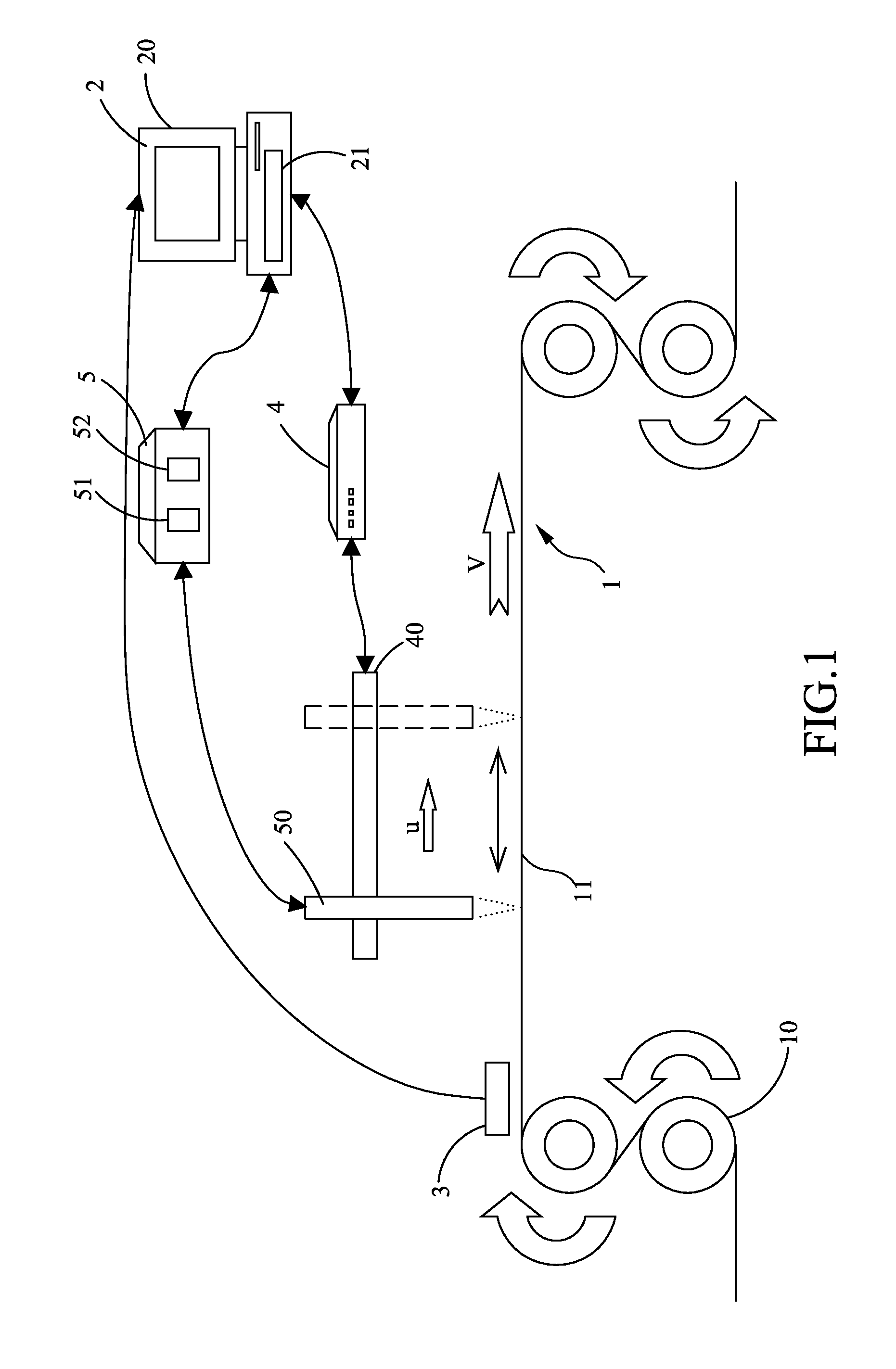
[0030]Please refer to FIG. 1, which is a schematic diagram showing an apparatus for measuring the topography of moving specimens according to a first embodiment of the present disclosure. The measuring apparatus in this embodiment is adapted to be applied to a transportation system 1 that can be a system composed of a specimen 11 in a roll-to-roll formation and a plurality of rollers 10 configured for unrolling and thus driving the specimen 11 to move.

[0031]In this embodiment, the measuring apparatus comprises: a control unit 2, at least one speed monitoring unit 3, a control module of linear movement 4, at least one first linear movement device 40, a first measurement control module 5 and at least one first measuring module ...


PUM


Abstract

A measuring method for topography of moving specimen and a measuring apparatus thereof is disclosed, providing a measuring module that moves along with a testing specimen to narrow relative velocity of the testing specimen and the measuring module so that the measuring module is able to have enough luminous intensity signal at the same position in time, to measure the topography or the thickness of the testing specimen.

Description

CROSS-REFERENCE TO RELATED APPLICATION[0001]This non-provisional application claims priority under 35 U.S.C. §119(a) on Patent Application No. 099146801 filed in Taiwan, R.O.C. on Dec. 30, 2010, the entire contents of which are hereby incorporated by reference.TECHNICAL FIELD[0002]The present disclosure relates to a method and an apparatus for measuring the topography of a moving specimen.TECHNICAL BACKGROUND[0003]Nowadays, continuous manufacturing processes, such as a roll-to-roll manufacturing process, has been vastly applied in various industries including flat panel display industry, flexible electronic industry and solar cell industry, etc., owing to their advantageous characteristics of being able to produce a mass of products in a comparatively short period of time.[0004]However, in those rapid mass production processes, it is possible to have a plenty of defective products being produced if a decision can not be made immediately for shutting down the production processes in ...

Claims


Application Information

Patent Timeline
Patent Type & Authority Applications(United States)
IPC IPC(8): G01B11/24
CPCG01B11/0691G01B11/245G01B11/24
Inventor KUO, SHIH-HSUANWANG, WEI-CHENG
Owner IND TECH RES INST
Why Eureka
Try Eureka