Fiber Ring Laser System and the Operation Method thereof

a fiber ring laser and fiber ring technology, applied in the direction of laser details, semiconductor lasers, electrical devices, etc., can solve the problems of not quite cost-effective, wavelength is not tunable, communication system becomes more and more complicated, etc., to facilitate laser activation, save power and cost

Inactive Publication Date: 2012-07-05
NAT TAIWAN UNIV OF SCI & TECH
View PDF3 Cites 6 Cited by
  • Summary
  • Abstract
  • Description
  • Claims
  • Application Information

AI Technical Summary

Benefits of technology

[0014]One advantage of the present invention is that the wavelength tunable range is about 1535 nm-1580 nm, covering the both C-band and L-band, which are commonly used in optical communication, and hence, the present invention can be widely applied in current communication system.
[0015]Another advantage of the present invention is that the line width of laser disclosed in the present invention is about 2.14-KHz, and that is better than 10-KHz, which is the line width provided by EDF.
[0016]Another advantage is that the wavelength tunable range reaches 45 nm, which is better than traditionally tunable fiber laser.
[0017]The other advantage of the present invention is that the critical (or driving) current is only 14 mA, which is lower than traditional tunable fiber laser, so as to facilitate to activate the laser to generate light, such that the present invention is more power-saving and cost-effective
[0018]Aforementioned description is to illustrate purposes of the present invention, technical characteristics to achieve the purposes, and the advantages brought from the technical characteristics, and so on. And the present invention can be further understood by the following description of the preferred embodiment accompanying with the claims.

Problems solved by technology

In pace with the development of technology, the requirement of communication for people surges day by day, and thus, the communication system becomes more and more complicated, and the desired bandwidth are increased accordingly.
This is not quite cost-effective.
But the semiconductor laser manufactured by identical process just emits particular wavelength, which means the wavelength is not tunable.
If there is a need to use different wavelength for increasing users of network, another particular process has to be provided for providing different semiconductor laser, and that is not cost-effective and not easy to be modified or expanded.
However, aforementioned fiber ring laser can only introduce an external modulator to load signals into light, which is very inconvenient.

Method used


Image

  • Fiber Ring Laser System and the Operation Method thereof
  • Fiber Ring Laser System and the Operation Method thereof
  • Fiber Ring Laser System and the Operation Method thereof

Examples


Embodiment Construction

[0025]Some sample embodiments of the invention will now be described in greater detail. Nevertheless, it should be recognized that the present invention can be practiced in a wide range of other embodiments besides those explicitly described, and the scope of the present invention is expressly not limited expect as specified in the accompanying claims.

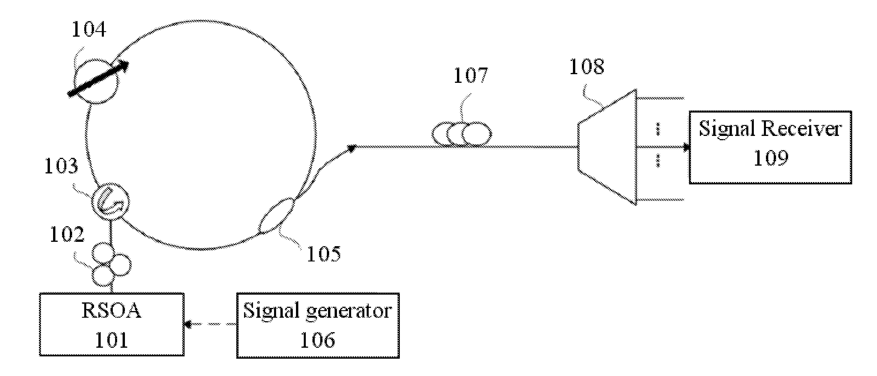
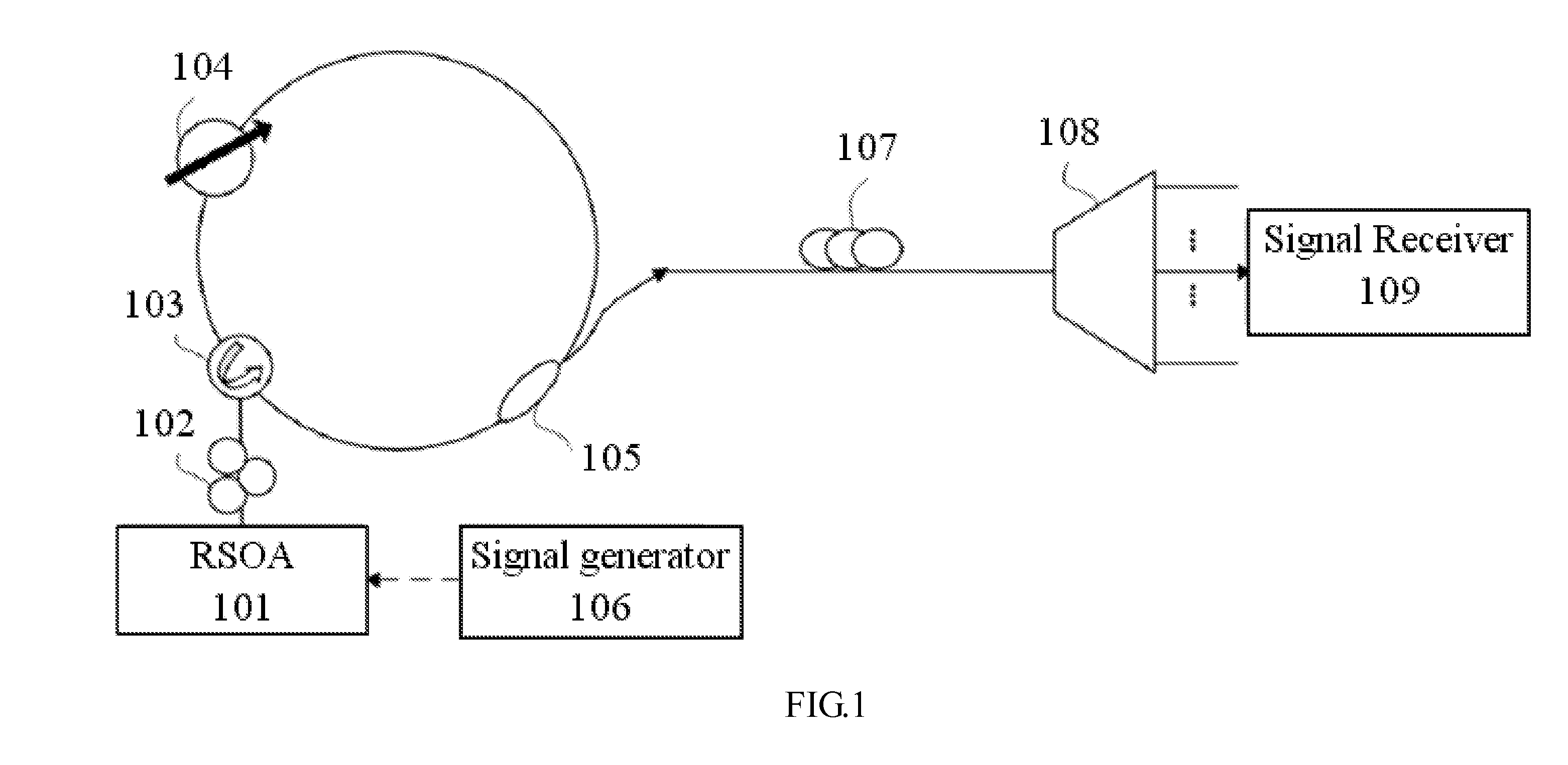
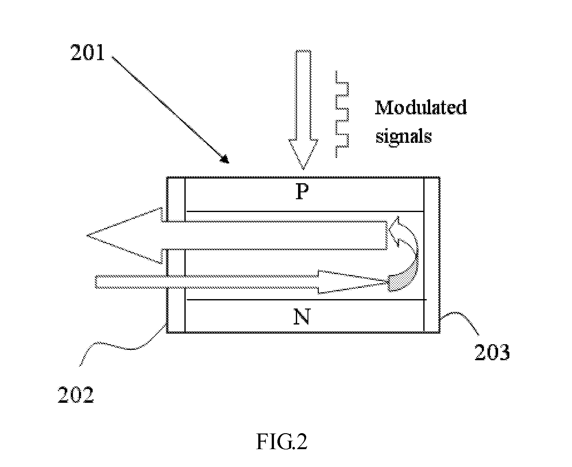
[0026]The present invention provides a wavelength-tunable directly modulated fiber ring laser system. Generally speaking, the system employs a RSOA (reflective semiconductor optical amplifier) and a tunable optical filter to construct a novel ring resonant cavity. Moreover, the present invention further couple the RSOA to a signal controller for receiving modulated signals and loading those signals into emitted light, thereby accomplishing the purpose of direct modulation.

[0027]Referred to FIG. 1, it shows a preferred embodiment of the fiber ring laser system disclosed by the present invention. As shown, the ring resonant cavity of the...


PUM


Abstract

A wavelength-tunable directly modulated fiber ring laser is provided. Generally speaking, the wavelength-tunable directly modulated fiber ring laser employs an RSOA (reflective semiconductor optical amplifier) and an OTF (optical tunable filter) to construct a novel ring resonant cavity. Additionally, a signal generator can be further employed to transmit modulated signals to the RSOA, whereby generating light wave with the modulated signals, so as to provide tunable wave-length and direct modulation at the same time.

Description

CROSS-REFERENCE TO RELATED APPLICATION[0001]This present application claims priority to TAIWAN Patent Application Serial Number 099147003, filed on Dec. 30, 2010, which is herein incorporated by reference.TECHNICAL FIELD[0002]The present invention generally relates to a fiber ring laser, in particular to a wavelength-tunable directly modulated fiber ring laser.DESCRIPTION OF RELATED ART[0003]In pace with the development of technology, the requirement of communication for people surges day by day, and thus, the communication system becomes more and more complicated, and the desired bandwidth are increased accordingly. In order to achieve a speedier and safer transmission, the optical fiber network system is widely utilized in recent years so as to meet aforementioned requirements.[0004]In the architecture of a traditional optical fiber network, the fiber transmits optical signals (or light) to a location distant from a user node, and subsequently converts those signals to electric si...

Claims


Application Information

Patent Timeline
Patent Type & Authority Applications(United States)
IPC IPC(8): H01S3/083H01S3/30
CPCH01S3/08013H01S3/08054H01S5/141H01S3/1062H01S5/06216H01S3/083
Inventor LIN, ZIH-RONGLIU, CHENG-KUANGJHANG, YU-JHUKEISER, GERD
Owner NAT TAIWAN UNIV OF SCI & TECH
Why Eureka
Try Eureka