Electroencephalogram measurement apparatus, method of estimating electrical noise, and computer program for executing method of estimating electrical noise

Active Publication Date: 2012-07-05
PANASONIC INTELLECTUAL PROPERTY MANAGEMENT CO LTD
View PDF4 Cites 31 Cited by
  • Summary
  • Abstract
  • Description
  • Claims
  • Application Information

AI Technical Summary

Benefits of technology

[0017]The present disclosure has been made in view of the above problems, and an objective thereo

Problems solved by technology

However, if the aforementioned physical input manipulations are required when manipulating a device whose main body has a small size and which is characterized to be handsfree, e.g., an HMD, the handsfree feature will be undermined, thus being ineffective.
Furthermore, in the case of manipulating a very small device such as a hearing aid, the operation buttons and/or dials will become very small, which will be inconvenient for frequent manipulations.
However, having to wear any electrodes for electroencephalogra

Method used


Image

  • Electroencephalogram measurement apparatus, method of estimating electrical noise, and computer program for executing method of estimating electrical noise
  • Electroencephalogram measurement apparatus, method of estimating electrical noise, and computer program for executing method of estimating electrical noise
  • Electroencephalogram measurement apparatus, method of estimating electrical noise, and computer program for executing method of estimating electrical noise

Examples


Example

Embodiment 1

[0133]FIG. 9 is a construction diagram of an electroencephalogram measurement apparatus 51 according to the present embodiment. FIG. 10 to FIG. 13 respectively show the detailed constructions of constituent elements of the present embodiment. Note that a user 100 is illustrated for convenience of explanation; it will be appreciated that the user 100 is no constituent element of the electroencephalogram measurement apparatus 51.

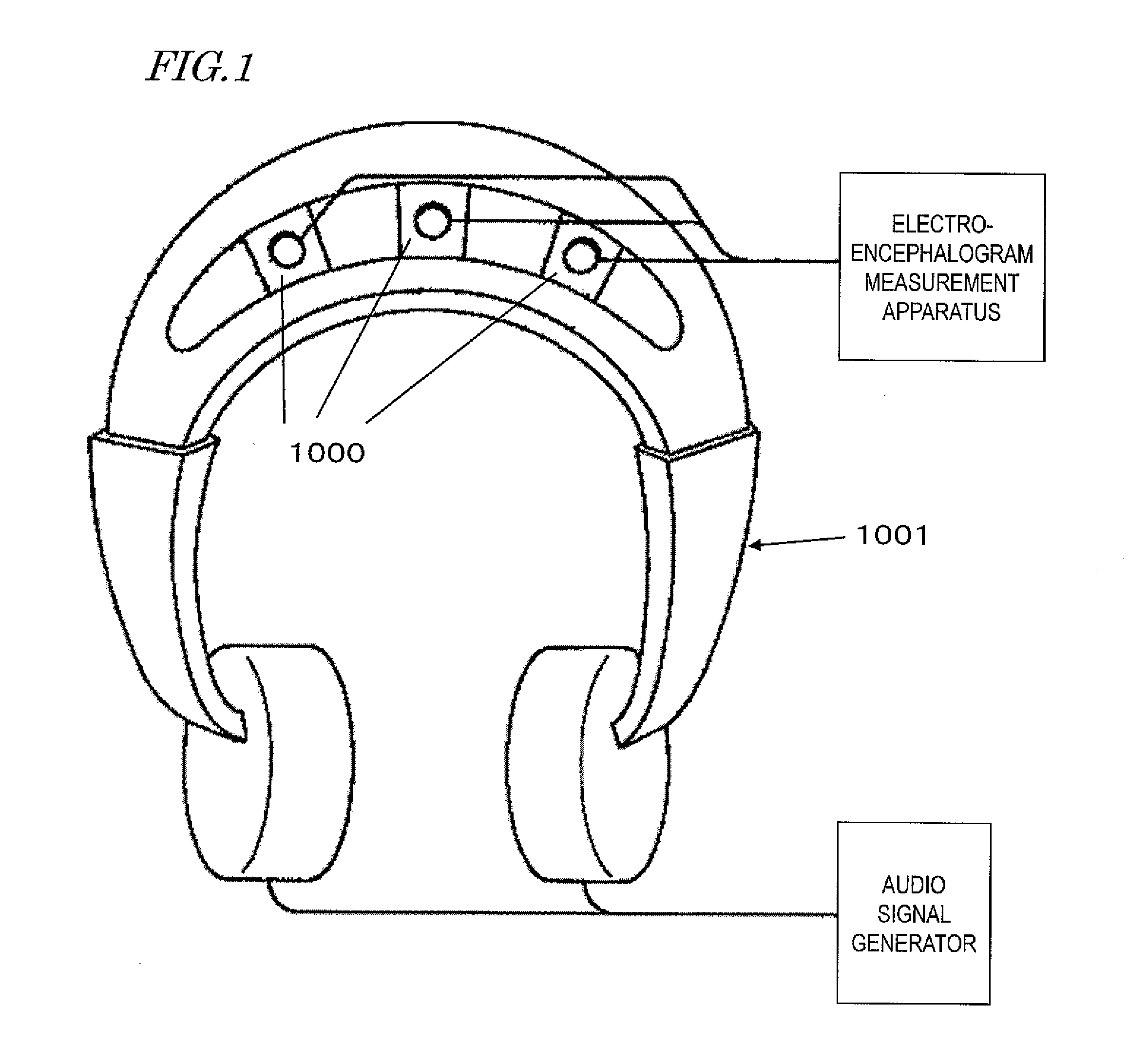
[0134]The present embodiment illustrates an example where user states are monitored based on an electroencephalogram and a device is automatically controlled in accordance with changes in the electroencephalogram. More specifically, it is an example where the sound volume of an acoustic output is manipulated in accordance with the frequency of occurrence of α waves in the electroencephalogram. Applications to an HMD as shown in FIG. 6 or a hearing aid as shown in FIG. 7 are possible.

[0135]The electroencephalogram measurement apparatus 51 includes a...

Example

Embodiment 2

[0197]FIG. 20 is a construction diagram showing an electroencephalogram measurement apparatus 52 of the present embodiment. FIG. 21 to FIG. 23 show the detailed constructions of constituent elements of the present embodiment. As for FIG. 20, FIG. 21, FIG. 22, and FIG. 23, elements similar to those of Embodiment 1 will be denoted by like numerals, and the descriptions thereof will be omitted.

[0198]The present embodiment illustrates an example where a user's intent is acquired with an electroencephalogram interface using an event-related potential in order to control a device. The present embodiment contemplates an HMD as shown in FIG. 6, and relies on the timing of highlighting an option on a display as a trigger for electroencephalogram cutting when acquiring an event-related potential.

[0199]The electroencephalogram measurement apparatus 52 includes an output control section 210, a waveform generation section 120, an electro-acoustic transducer 130, an amplitude envelope...

Example

Embodiment 3

[0289]FIG. 33 is a construction diagram of an electroencephalogram measurement apparatus 54 according to Embodiment 3. As compared to the electroencephalogram measurement apparatus 53 according to a variant of Embodiment 2, the noise estimation section 350 in the variant of Embodiment 2 is omitted from the electroencephalogram measurement apparatus 54 of the present embodiment. Moreover, a determination criteria setting section 480 is provided instead of the noise subtraction section 180, and a determination section 490 is provided instead of the determination section 390. Otherwise, the electroencephalogram measurement apparatus 54 of the present embodiment has an identical construction to the construction of the electroencephalogram measurement apparatus 53 according to the variant of Embodiment 2. The constituent elements surrounded by the broken line are similarly implementable by a CPU and / or a memory.

[0290]As in the above embodiment, the present embodiment also ill...


PUM


Abstract

An electroencephalogram measurement apparatus includes: an electroencephalogram measurement section for measuring an electroencephalogram of a user by using a plurality of electrodes; an electro-acoustic transducer for presenting an acoustic signal to the user, the electro-acoustic transducer being in a vicinity of at least one electrode among the plurality of electrodes while the electroencephalogram measurement section is worn by the user; an amplitude envelope extraction section for extracting an amplitude envelope of the acoustic signal presented by the electro-acoustic transducer; a frequency analysis section for applying a frequency analysis to the amplitude envelope extracted by the amplitude envelope extraction section; and a noise estimation section for estimating an electrical noise which is mixed at the at least one electrode by using a previously provided set of transform rules and the extracted amplitude envelope.

Description

[0001]This is a continuation of International Application No. PCT / JP2011 / 002189, with an international filing date of Apr. 13, 2011, which claims priority of Japanese Patent Application No. 2010-103144, filed on Apr. 28, 2010, the contents of which are hereby incorporated by reference.BACKGROUND OF THE INVENTION[0002]1. Field of the Invention[0003]The present invention relates to a technique of reducing influences of acoustic signals in electroencephalogram measurement.[0004]2. Description of the Related Art[0005]In recent years, due to decreases in the size and weight of devices, wearable devices such as stereo headphone-type music players and head-mount displays (hereinafter also referred to as “HMDs”) are gaining prevalence.[0006]Usually, as an interface with which to manipulate a device, physical input manipulations using an input device have been employed, e.g., “pressing a button”, “moving a cursor and making a confirmation”, or “manipulating a mouse while watching a screen”. ...

Claims


Application Information

Patent Timeline
IPC IPC(8): A61B5/048A61B5/0484A61B5/374
CPCA61B5/0478A61B5/048A61B5/726A61B5/7203A61B5/04845A61B5/374A61B5/38A61B5/291
Inventor KATO, YUMIKOADACHI, SHINOBUTERADA, YOSHIHISAMORIKAWA, KOJI
Owner PANASONIC INTELLECTUAL PROPERTY MANAGEMENT CO LTD
Why Eureka
Try Eureka