Microwave Hyperthermia Treatment System

Active Publication Date: 2012-07-05
WISCONSIN ALUMNI RES FOUND
17 Cites 34 Cited by

AI-Extracted Technical Summary

Problems solved by technology

As a practical matter, it is impossible to find a given set of phase and amplitude values that focus microwave radiation for an arbitrary treatment pattern while completely suppressing the deposition of micr...

Method used

[0061]Referring now to FIGS. 3 and 7, at process block 85, the beamformers 84 may be arranged in order and given durations to create a treatment schedule 86 that will be used to control the antennas 14 during treatment of the patient. Typically the treatment schedule 86 will have a duration of greater than one second to permit simplified control of the radio frequency amplifier but shorter than a thermal time constant of the tissue. In one embodiment, the treatment schedule 86 may be cycled periodically for multiple times to provide the desired length of treatment but also to provide rapid switching among beamformers 84 for more consistent temperature generation.
[0062]The process of ordering and determining the length of time for each beamformer 84 in the treatment sc...

Benefits of technology

[0006]The present inventors have recognized that the unwanted heated zones can be minimized by cycling through different antenna array settings each having a common treatment zone but providing relative “cold spots” or suppression region...

Abstract

A microwave hyperthermia treatment system employs a set of antennas individually controllable to provide different phase and amplitude outputs and controlled to cycle through different sets of phases and amplitudes over time to minimize the effect of hotspots formed by any given set of phases and amplitudes and creating limiting high temperatures outside of a desired treatment area.

Application Domain

DiagnosticsSurgical instrument details +3

Technology Topic

EngineeringPhason +4

Image

  • Microwave Hyperthermia Treatment System
  • Microwave Hyperthermia Treatment System
  • Microwave Hyperthermia Treatment System

Examples

  • Experimental program(1)

Example

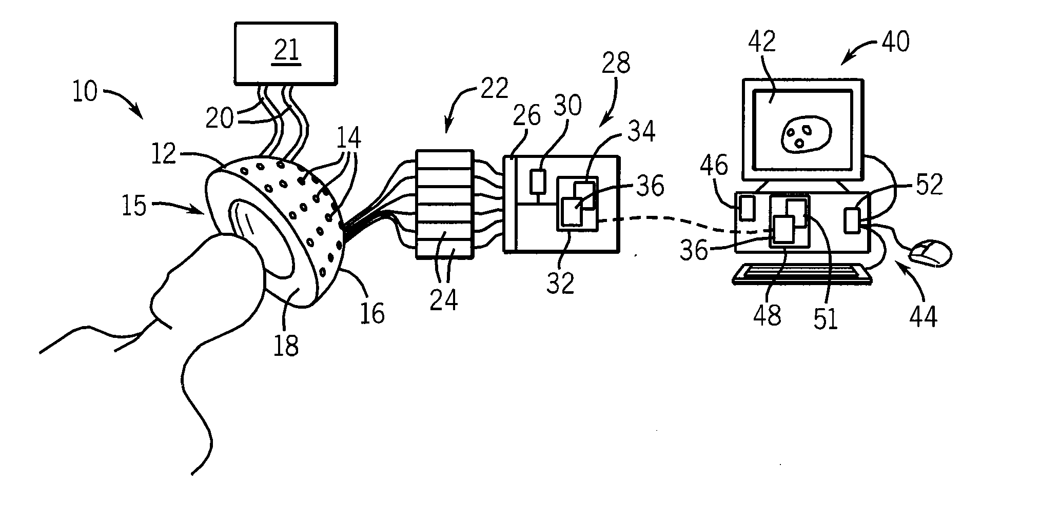
[0047]Referring now to FIG. 1, a hyperthermia system 10 may provide an antenna fixture 12 supporting a plurality of antennas 14 about a treatment volume 15. In one embodiment, the treatment volume may be defined by a substantially hemispherical shell 16 whose inner surface may contain a collar 18 receiving and supporting the top of the patient's head. The collar may be filled with de-ionized water that may be circulated through connecting hoses 20 with a cooler/pump 21 providing skin cooling of at approximately 15 degrees centigrade of the patient's head to minimize surface heating of the skin by microwave energy from the antennas 14 as will be described.
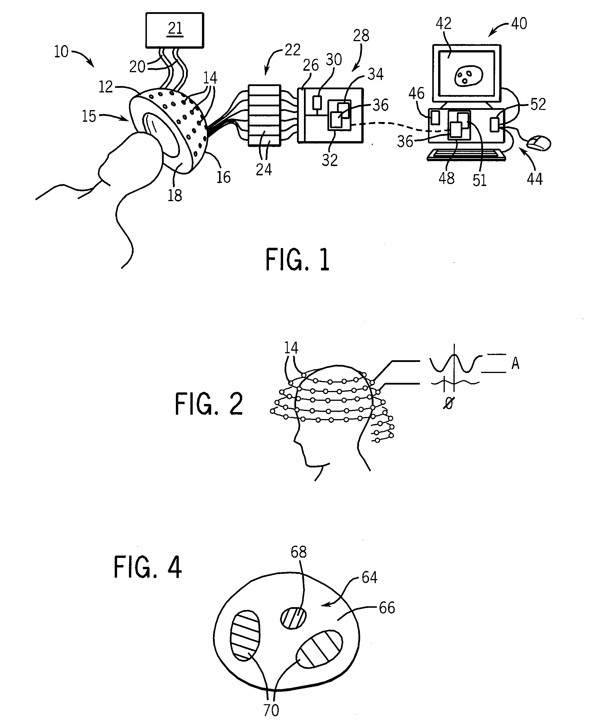
[0048]Referring also to FIG. 2, the antennas 14 may be arranged at multiple heights along an inferior superior axis of the patient and about an upper portion of the patient's head. The antennas 14 preferably direct microwave energy inward toward the treatment volume 15 and may, for example, be microwave horns or patch antennas or other antennas of a type known in the art and are spaced to provide for substantially uniform separation of less than six centimeters.
[0049]In one embodiment, 134 antennas 14 operating at 1 GHz are distributed evenly across five elliptical rings and three partial elliptical rings, each ring separated by two centimeter elevational spacing, the antenna-to-antenna spacing on each ring being approximately four centimeters.
[0050]Referring still to FIGS. 1 and 2, each antenna 14 may be connected to a radiofrequency power source 22 providing independent phase (phi) and amplitude (A) control of the radiofrequency power applied to the antenna. The radiofrequency power source 22 may provide a separate radiofrequency amplifier/synthesizer 24 for each antenna 14 or may use a single radiofrequency power source with separate amplitude and phase shifters. In one embodiment, a set of discrete phases and amplitudes may be implemented in a switching fashion.
[0051]The radiofrequency power source 22 may be controlled by a treatment controller 28 via an interface board 26, for example, providing a multiplexed A/D converter outputting phase and amplitude values from the treatment controller 28. The treatment controller 28 may include a processor 30 communicating with a memory 32 holding a stored program 34 and treatment plan data 36 describing a treatment schedule of changing phases and amplitudes of microwave frequency to be applied to the antennas 14 during treatment.
[0052]The treatment plan data 36 may be developed on the treatment controller 28 but preferably is developed off-line on a separate workstation 40 having a display 42 for displaying treatment maps for physician input, as will be described, generated by a communicating standard desktop computer 44 also having a processor 46, a stored memory 48 holding a treatment planning program 51 and the treatment plan data 36, the latter which may be transferred to treatment controller 28. The desktop computer 44 may also communicate with input devices 50 by interface 52 according to well understood techniques for physician input as will be described. It will be appreciated that the processing and data storage required by the present invention may be freely distributed among one or more processors and different types of computers according to well-understood techniques.
[0053]Referring now to FIG. 3, in developing treatment plan data 36, the treatment planning program 51 may first receive MRI input data, as indicated by process block 60, of the particular patient to be treated. The treatment plan data may be registered to fiducial points such as bony prominences of the patient's skull or points on a stabilization fixture also alignable with the fixture 12. This MRI data may be displayed on the display 42 for reference by a physician for development of a treatment map, to be described, and is preferably applied to a stored encyclopedia of tissue types to identify thermal and electrical characteristics of the tissue in different regions of the patient's brain.
[0054]At process block 62, the treatment map 64 is prepared using the workstation 40, for example, by displaying successive slices of a tissue region 66 of the patient as shown in FIG. 4 which together describe volumetric data encompassing a tissue subject to microwave exposure. The slices may be reviewed by the physician to define a treatment region 68 within the tissue region 66 where elevated temperatures are desired for hyperthermia treatment. The boundaries of the treatment region 68 and desired minimum temperatures in one or more zones of this treatment region 68 may be entered by the physician or automatically set.
[0055]Optionally, the physician may also define one or more protection regions 72 to which maximum desired temperatures or other temperature constraints, such as measures of uniformity or the like, may be applied. Generally, the tissue region 66 outside the treatment region 68 will be limited to a temperature of 41 degree centigrade or less.
[0056]At process block 73, the treatment-planning program 51 generates an initial “beamformer” being a set of independent amplitude and phases of microwave electromagnetic radiation to be applied to each of the antennas 14. This initial beamformer is selected to maximize the fraction of deposited power density in the treatment region 68 with respect to the deposited power density outside the treatment region 68, although other similar constraints may be used that promote a focusing of power deposition in the treatment region 68. This beamformer may be generated, for example, by treating a set of linear equations providing phase and amplitude values for each antenna and incorporating microwave propagation characteristics of the patient tissue derived from the MRI data of process block 60 between each antenna and each voxel of tissue in the tissue region 66.
[0057]Referring to FIGS. 3 and 5, at process block 74 tissue temperatures generated by the initial beamformer are then modeled using the thermal and electrical characteristics of the tissue of the patient to provide a power deposition pattern 76 (depicted two-dimensionally but preferably three-dimensional) that shows deposited power or tissue temperature at different portions of the tissue region 66 for predetermined duration of treatment, for example, the time required to raise the temperature within the treatment region 68 to 43-44 degrees centigrade. Typically, this power deposition pattern 76 will also show one or more hotspots 78a-c being areas of elevated power deposition or temperature outside of the treatment region 68. For example, hotspots 78 may be defined as voxels in the head but outside of the treatment region 68 whose temperature exceeds 41 degrees centigrade or voxels exceeding a temperature of a susceptible region defined by the physician.
[0058]Referring now to FIGS. 3 and 6, at succeeding process block 77, a suppression region 80 may be defined around each hotspot 78. In one embodiment, for convenience, these suppression regions 80 are defined as spheres of approximately ten percent of the brain volume. Each suppression region 80 may be centered on a peak temperature of each hotspot 78. For hotspots 78 larger than a suppression region 80, such as hotspot 78a as depicted, an iterative process may be used where a first suppression region 80a is centered on a peak temperature of the hotspot 78a and then subsequent suppression regions 80b and 80c are applied to portions of the hotspot 78a not already circumscribed by a suppression region 80a centered on a peak temperature of those remaining regions, and so forth until all hotspots 78 are completely covered.
[0059]Referring now to FIG. 7, additional beamformers 84 are then generated, each defining the phase and amplitude of power at a respective antenna 14 using a process similar to that described with respect to process block 73 but with an optimization that maximizes power to the treatment region 68 and limits power to the suppression regions 80. For example, the fraction described above with respect to the initial beamformer may be used with additional weighting provided to the desired suppression regions 80 of the tissue regions 66 outside of the treatment region 68.
[0060]In one embodiment, different beamformers 84 may be generated each preserving a different suppression region 80 associated with each of the suppression regions identified in process block 77 to produce a number of beamformers 84 equal to the number of desired suppression regions 80. In addition, one beamformers 84 may be developed providing suppression of power in the union or combinations of all suppression regions 80, and one beamformer 84 may be developed without consideration of any of the suppression region 80 to emphasize treatment of the treatment region 68. In a general case, some of these beamformers 84 preserving suppression regions 80 will generate power deposition patterns 76 having additional hotspots 78′. Typically these hotspots 78′ will be in different locations than the hotspots 78 of the initial beamformer. More typically, however, beamformers 84 emphasizing suppression regions 80 will have no new hotspots 78 or minor hotspots 78 beyond those identified at process block 74.
[0061]Referring now to FIGS. 3 and 7, at process block 85, the beamformers 84 may be arranged in order and given durations to create a treatment schedule 86 that will be used to control the antennas 14 during treatment of the patient. Typically the treatment schedule 86 will have a duration of greater than one second to permit simplified control of the radio frequency amplifier but shorter than a thermal time constant of the tissue. In one embodiment, the treatment schedule 86 may be cycled periodically for multiple times to provide the desired length of treatment but also to provide rapid switching among beamformers 84 for more consistent temperature generation.
[0062]The process of ordering and determining the length of time for each beamformer 84 in the treatment schedule 86 takes into account the thermal model of the tissue with respect to its cooling and heating under the application of power. This treatment schedule 86 may be determined automatically by an optimization process such as linear programming according to a goal of maximizing a uniformity of the heating of the tissue region 66 outside of the treatment region 68 or minimizing an error (for example, the least squared error) between the average temperature outside the treatment region 68 and the desired treatment map 64. The determination of the treatment schedule 86 may also take into account the historical thermal state of the tissue implicit in the ordering to promote time uniformity in the produced temperatures, something that is also promoted by short time slices.
[0063]Referring now to FIG. 8, an example treatment schedule 86 will cycle through different beamformers 84 (indicated on the vertical axis) for different periods of time (indicated on the horizontal axis) according to this optimization. In this example, beamformer number 13 was optimized to cover all of the suppression regions 80 and accounts for more than half the duration of the treatment schedule 86. Notably, some beamformers 84 are not used or given zero weighting.
[0064]Once the sequence of the treatment schedule 86 is complete, the treatment schedule 86 may be modeled and the resulting temperature distributions and other treatment statistics (e.g. maximum temperatures and durations) reviewed by the physician as indicated by process block 88. If the treatment schedule 86 is approved, the treatment plan may be output as the treatment plan data 36 of FIG. 1 as indicated by process block 94 to provide real-time control of the hyperthermia system 10.
[0065]Referring again to FIG. 3, it will be recognized that at process block 88, the process of process blocks 73, 74, 77, 85, and 88 may be repeated, for example, with a different initial beamformer 84 at process block 73 or different linear programming criteria or the like to provide for an iterative process or alternative solutions meeting different goals. Alternatively, or in addition, this iteration may be used in a more general global optimization approach described below.
[0066]Referring now to FIG. 9, while the present invention has provided one method of choosing and ordering multiple beamformers 84, using an initial definition of a beamformer and a matching of hotspots 78 to suppression regions 80, it will be appreciated that other mathematical techniques may also be used for this purpose of creating an evolving sequence of beamformers. Such techniques include general global optimization techniques including stochastic optimization methods such as simulated annealing and the like. Generally each of these concepts will provide an initial seed set 96 of phases and amplitudes Wi for the antennas 14 for different times (t) and will apply them to an electromagnetic model of the tissue 98 and a thermal model of the tissue 100 to provide for a modeled temperature profile 102. This temperature profile may be analyzed by an objective function 104 (for example considering any or all of peak temperature values, tissue damage, treatment speed, uniformity, accuracy and the like) typically incorporating input information 106 provided by the physician indicating desired treatment zones temperatures and metrics. The output of the objective function is used to modify the seed set 96 and its time sequence until the desired optimization is produced as measured by a threshold applied to the output of the objective function 104.
[0067]Importantly, the present invention produces not a single set of phases and amplitudes but a schedule of different phases and amplitudes reflecting the fact that a single such set of phases and amplitudes necessarily results in the creation of limiting hotspots. While the application of the beamformers per FIG. 8 is shown in discrete steps, it will be appreciated that the transitions in phase and amplitude may implemented as smooth transitions between states if desired. Nevertheless, the present invention anticipates a finite number of calculated beamformers.
[0068]It will further be appreciated that the invention is not limited to antenna arrays but that other means for producing spatially directive patterns, such as microwave lenses may be used. In addition, the invention may employ a spatially scanning (e.g., mechanically moved) set of antennas may be used to provide a time-varying spatial pattern of energy providing an effective antenna array of multiple emitters. That is, the set of microwave emitters may be implemented by as few as one emitter moved between locations and provided different amplitudes and phases of microwave power.
[0069]It should be understood that the invention is not limited in its application to the details of construction and arrangements of the components set forth herein. The invention is capable of other embodiments and of being practiced or carried out in various ways. Variations and modifications of the foregoing are within the scope of the present invention. It also being understood that the invention disclosed and defined herein extends to all alternative combinations of two or more of the individual features mentioned or evident from the text and/or drawings. All of these different combinations constitute various alternative aspects of the present invention. The embodiments described herein explain the best modes known for practicing the invention and will enable others skilled in the art to utilize the invention.

PUM

no PUM

Description & Claims & Application Information

We can also present the details of the Description, Claims and Application information to help users get a comprehensive understanding of the technical details of the patent, such as background art, summary of invention, brief description of drawings, description of embodiments, and other original content. On the other hand, users can also determine the specific scope of protection of the technology through the list of claims; as well as understand the changes in the life cycle of the technology with the presentation of the patent timeline. Login to view more.

Similar technology patents

Compound and method for treatment of movement disorders

ActiveUS20190201463A1effective treatmentunwanted effect
Owner:KARIMAN ALEXANDER

Combination therapy for treating or preventing cancer

InactiveUS20210060093A1effective treatment
Owner:4D PHARMA RES LTD +1

Combination therapy with il-12

InactiveUS20160022777A1effective treatment
Owner:NKT THERAPEUTICS

Classification and recommendation of technical efficacy words

Why Eureka
Try Eureka