
Generating inviscid and viscous fluid-flow simulations over an aircraft surface using a fluid-flow mesh

Active Publication Date: 2012-07-05
AERION INTPROP MANAGEMENT CORP
View PDF17 Cites 19 Cited by
  • Summary
  • Abstract
  • Description
  • Claims
  • Application Information

AI Technical Summary

Benefits of technology

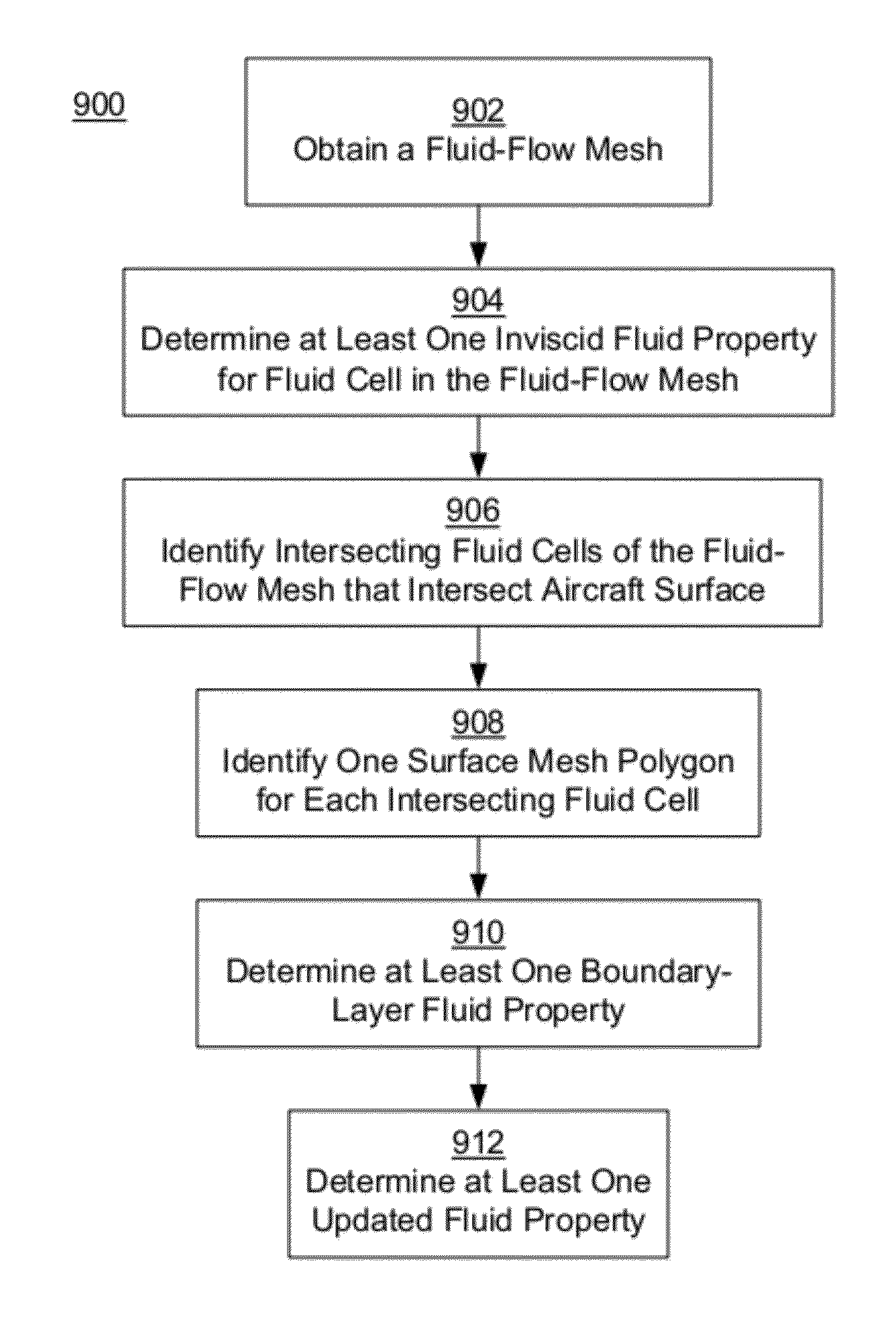
[0011]One exemplary embodiment includes a computer-implemented method of generating a fluid-flow simulation over a computer-generated aircraft surface, the computer-generated aircraft surface comprised of a surface mesh of surface mesh polygons. A fluid-flow mesh is obtained for simulating a fluid flow over the aircraft surface, the fluid-flow mesh comprising a plurality of fluid cells. At least one inviscid fluid property for each of the fluid cells is determined using an inviscid fluid simulation that does not simulate fluid viscous effects. A set of intersecting fluid cells, of the plurality of fluid cells, that intersects the aircraft surface is identified. One sur

Problems solved by technology

Because a single CFD simulation module may include millions of individual fluid cells, the complexity of the relationship between fluid cells can have a large effect on the computational efficiency of the simulation.
Complex CFD simulation modules can be computationally expensive and require hours or even days to execute using high-performance computer processing hardware.
However, more sophisticated simulation modules are also likely to require more computing resources and therefore require more time to solve.
Using multiple CFD simulation modules may be difficult, particularly if the CFD simulation modules were not initially designed to work together.

Method used


Image

  • Generating inviscid and viscous fluid-flow simulations over an aircraft surface using a fluid-flow mesh
  • Generating inviscid and viscous fluid-flow simulations over an aircraft surface using a fluid-flow mesh
  • Generating inviscid and viscous fluid-flow simulations over an aircraft surface using a fluid-flow mesh

Examples


Embodiment Construction

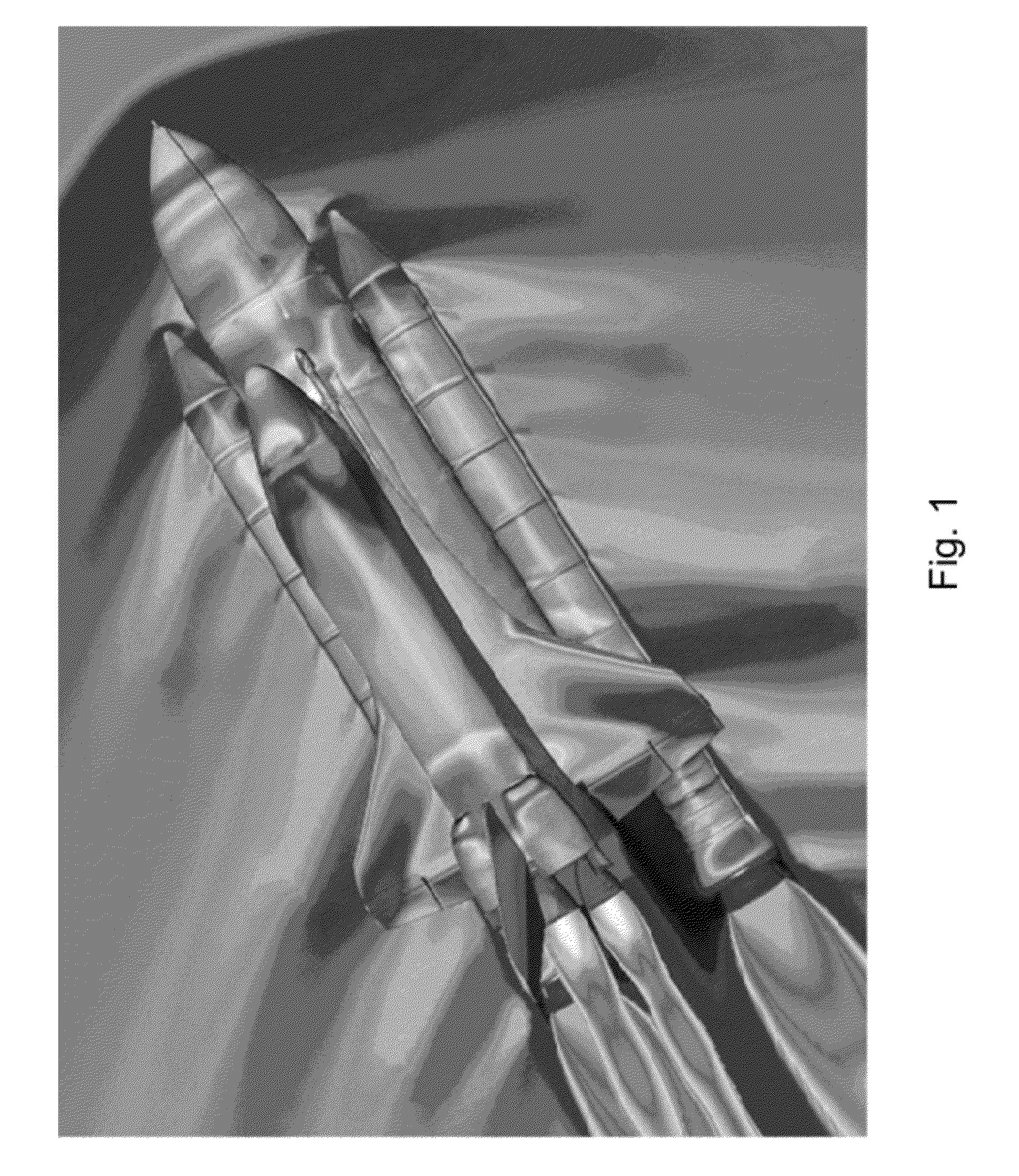
[0025]As discussed above, a computer-generated simulation can be used to analyze the aerodynamic performance of a proposed aircraft surface, such as a wing or control surface. Using known geometry modeling techniques, a computer-generated aircraft surface that represents the outside surface of the proposed aircraft can be constructed. FIG. 1 depicts an exemplary computer-generated aircraft surface of the Space Shuttle orbiter vehicle, external tank, and twin solid rocket boosters. A CFD fluid simulation module has been applied using the computer-generated aircraft surface of the Space Shuttle orbiter to predict the fluid properties of an exemplary fluid flow.

[0026]As shown in FIG. 1, the results of the simulation can be visually represented as shaded regions on the computer-generated aircraft surface of the Space Shuttle. Different shades represent the predicted pressure distribution resulting from the simulated fluid flow. In FIG. 1, transitions between the shaded regions represent...


PUM


Abstract

Fluid-flow simulation over a computer-generated aircraft surface is generated using inviscid and viscous simulations. A fluid-flow mesh of fluid cells is obtained. At least one inviscid fluid property for the fluid cells is determined using an inviscid fluid simulation that does not simulate fluid viscous effects. A set of intersecting fluid cells that intersects the aircraft surface are identified. One surface mesh polygon of the surface mesh is identified for each intersecting fluid cell. A boundary-layer prediction point for each identified surface mesh polygon is determined. At least one boundary-layer fluid property for each boundary-layer prediction point is determined using the at least one inviscid fluid property of the corresponding intersecting fluid cell and a boundary-layer simulation that simulates fluid viscous effects. At least one updated fluid property for at least one fluid cell is determined using the at least one boundary-layer fluid property and the inviscid fluid simulation.

Description

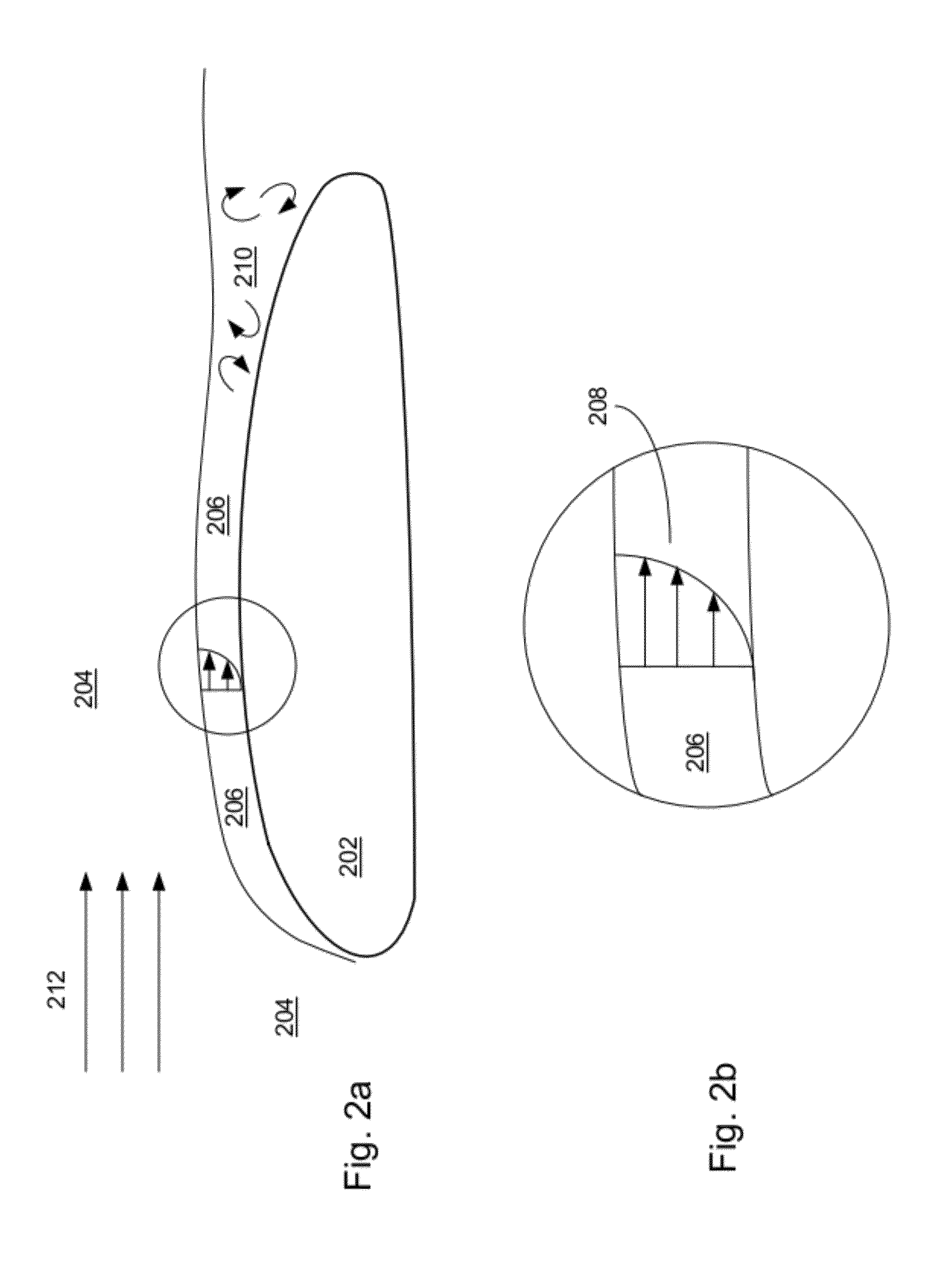
BACKGROUND[0001]1. Field[0002]This application relates generally to simulating a fluid flow over an aircraft surface and, more specifically, to generating both inviscid and viscous fluid-flow simulations using a fluid-flow mesh.[0003]2. Description of the Related Art[0004]Aerodynamic analysis of an aircraft moving through a fluid typically requires an accurate prediction of the properties of the fluid surrounding the aircraft. Accurate aerodynamic analysis is particularly important when designing aircraft surfaces, such as the surfaces of a wing or control surface. Typically, the outer surface of a portion of the aircraft, such as the surface of a wing, is modeled, either physically or by computer model, so that a simulation of the fluid flow can be performed and properties of the simulated fluid flow can be measured. Fluid-flow properties are used to predict the characteristics of the wing including lift, drag, boundary-layer velocity profiles, and pressure distribution. The flow p...

Claims


Application Information

Patent Timeline
IPC IPC(8): G06G7/57
CPCG06F17/5018G06F17/5095G06F2217/16G06F19/704G06F17/5009G06F17/18G06F2217/46G16C20/30G06F30/23G06F30/15G06F2113/28G06F2111/10G06F30/20Y02T90/00G06F30/28G06F2113/08
Inventor RODRIGUEZ, DAVID L.STURDZA, PETER
Owner AERION INTPROP MANAGEMENT CORP
Learn More