Controlled feed-rate shredding

a technology of feed rate and shredding speed, which is applied in the field of rotary shear shredding, can solve the problems of inability to essentially shred process materials, cost-intensive redesign of shredder cutting geometry, and over-sizing of design shredder drives, etc., and achieves the effect of improving rotary shear shredding

Active Publication Date: 2012-07-12
SSI SHREDDING SYST
View PDF3 Cites 8 Cited by
  • Summary
  • Abstract
  • Description
  • Claims
  • Application Information

AI Technical Summary

Benefits of technology

[0015](a) a torque load sensor at all times operatively connected to the drive motor which is drivingly connected to the selected main shaft, operable effectively to monitor, continuously during shredding, the torque load experienced by that shaft,
[0017](c) an algorithmically programmed digital computer operatively connected both to the sensor and to the controller, operable, based upon the selected main shaft torque load monitored by the sensor, and employing the controller in relation to the drive motor which is drivingly connected to the selected controlled shaft, to control selectively, in a manner variably differentiating the relative rotational motions of the two shafts, the rotational speed and, if needed, the rotational direction of the selected controlled shaft in a way effective to achieve a desired, appropriate and controlled, material-shredding feed-rate through the shredding zone.

Problems solved by technology

These two factors—feed style and material type—cause significant shredder torque demand variations that typically lead to expensive design over-sizing of shredder drives, and to costly revising of shredder-cutting geometry, such that the toughest material to be processed can confidently and correctly be shredded.
As those skilled in the relevant art well know, some process materials are essentially unable to be shredded due their propensity to self-feed.

Method used


Image

  • Controlled feed-rate shredding
  • Controlled feed-rate shredding

Examples


Embodiment Construction

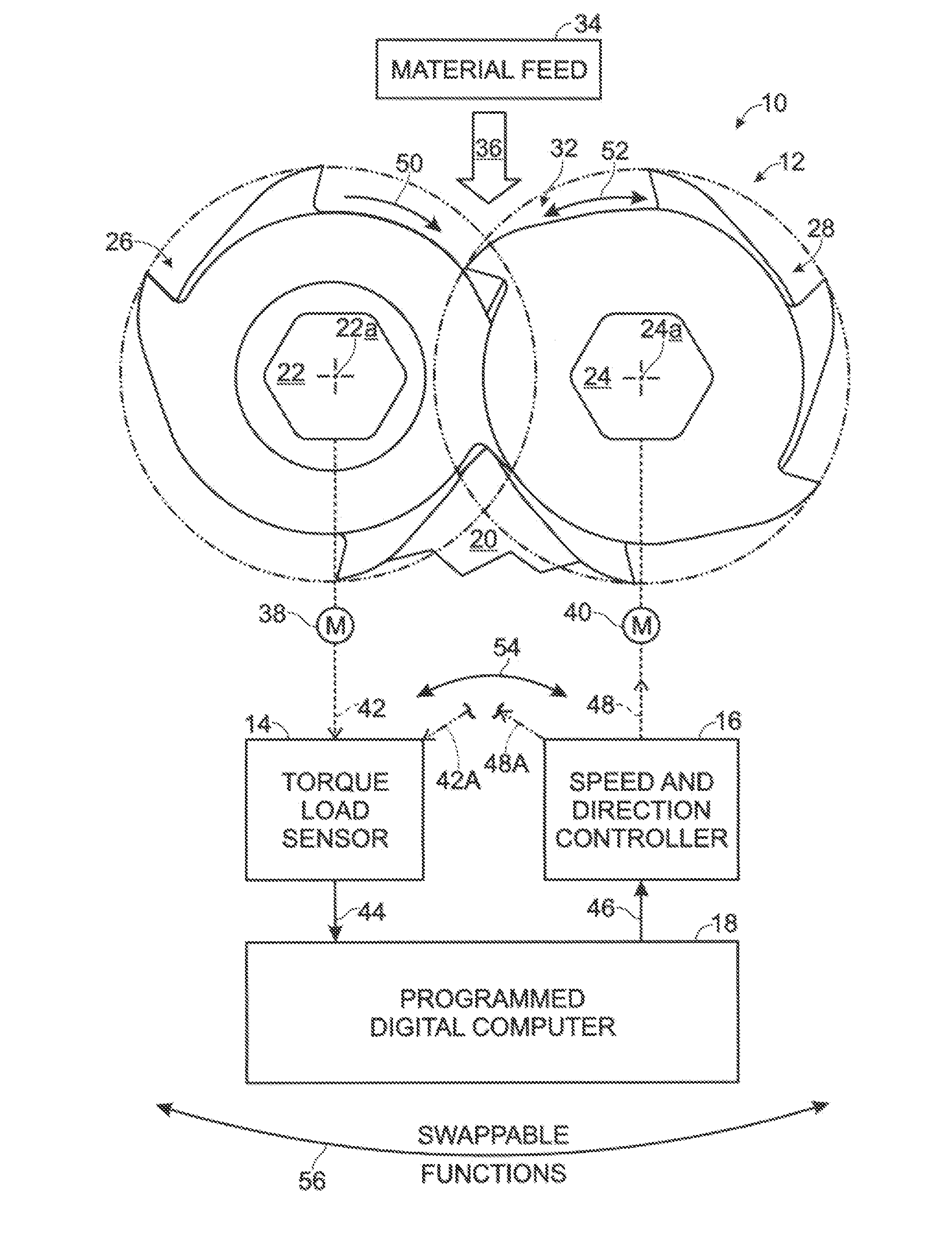
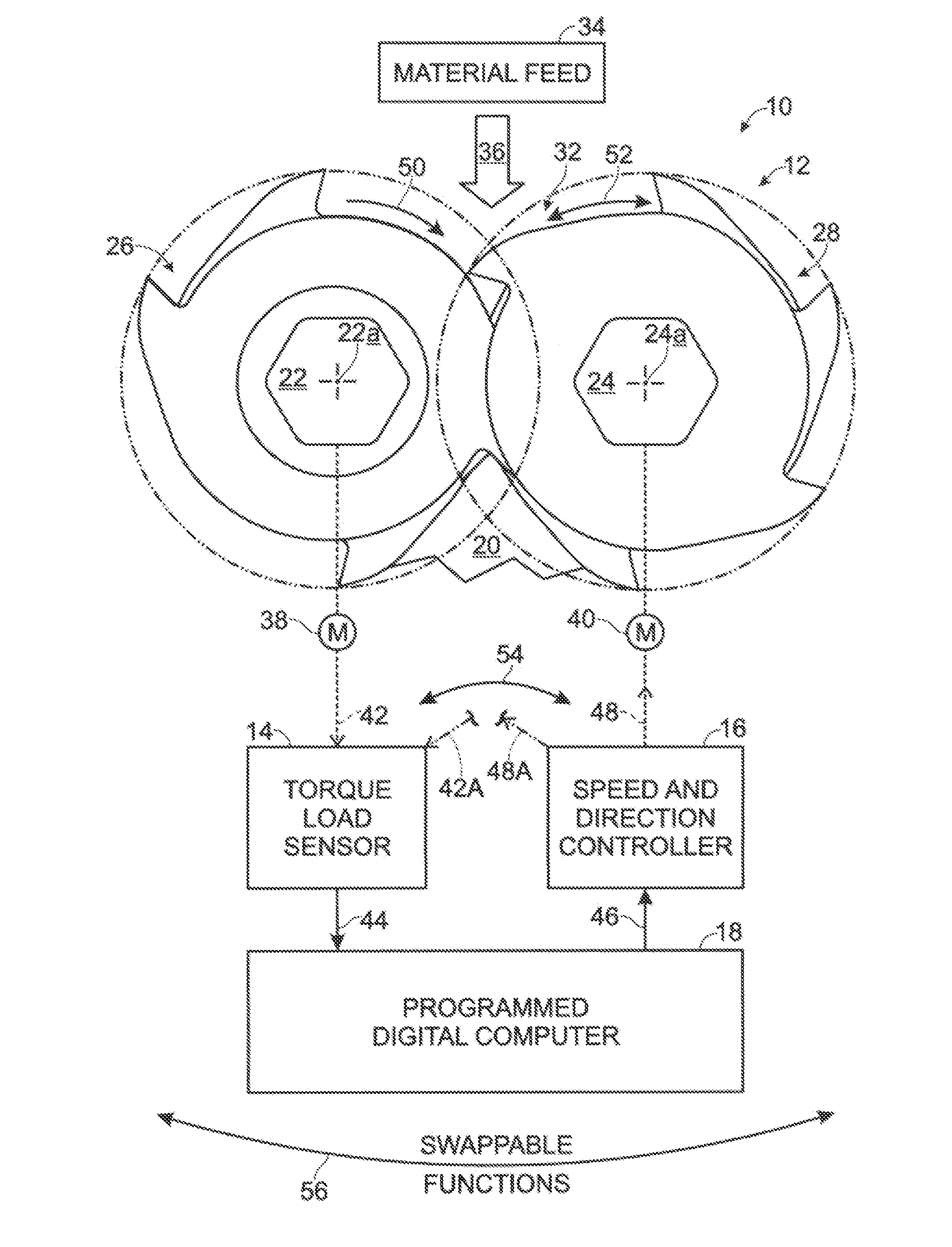
[0024]Turning now to the drawing, and describing from one systemic and methodologic point of view using this drawing for both of these aspects of the present invention, what is shown therein, indicated generally at 10 is a preferred and best-mode form of a rotary shear-shredding system, and an associated methodology, constructed in accordance with the invention for the controlled feed-rate shredding of material fed into the shredding zone in a rotary shear shredder. System 10, described now chiefly, and immediately below, from a systemic perspective, and recognizing that this systemic-perspective description also “effectively” describes the associated companion methodology (also designated 10 herein), includes, fragmentarily and somewhat schematically illustrated, an otherwise conventional (“otherwise”, or other, than as this shredder is associated combinationally with other collaborative structure now to be described) two-shaft, rotary shear shredder 12, a torque load sensor 14, re...


PUM


Abstract

A method, and method-implementing system structure, for metering the flow of material through the shredding zone in a rotary shear shredder, which zone is defined, at least in part, by confrontingly rotating knives that are carried on a pair of adjacent, power-driven, nominally matched-motion counter-rotating shafts. The method includes holding the speed and rotational direction of one of the shafts essentially constant while selectively varying, in a manner variably differentiating the relative rotational motions of the two shafts, the speed, and under certain circumstances also the direction, of rotation solely of the other shaft.

Description

CROSS REFERENCE TO RELATED APPLICATION[0001]This application claims filing-date priority to U.S. Provisional Patent Application Ser. No. 61 / 430,975, filed Jan. 8, 2011, for “Controlled Feed-Rate Shredding”, the entire disclosure content in which is hereby incorporated herein by reference.BACKGROUND AND SUMMARY OF THE INVENTION[0002]This invention pertains to an improvement in rotary shear shredding, and specifically to an improved system, and to an associated, improved methodology, based upon controlled-feed-rate shredding of material in a rotary shear shredder. More particularly, it concerns such a system and methodology which involve metering the flow of material through the shredding (shearing) zone in such a shredder by variably differentiating, through the making of single-shaft motion adjustments, the relative rotational motions of the usual, two, power-driven, conventionally matched-motion counter-rotating, knife-carrying shafts which, with their respectively carried, circula...

Claims


Application Information

Patent Timeline
Patent Type & Authority Applications(United States)
IPC IPC(8): B02C23/02B02C25/00
CPCB02C18/142B02C2018/164B02C25/00
Inventor NEUNZERT, MICHAEL G.
Owner SSI SHREDDING SYST
Why Eureka
Try Eureka