
System and method for monitoring current drawn by a protected load in a self-powered electronic protection device

a technology of electronic protection device and protection load, which is applied in emergency protection circuit arrangement, spectral/fourier analysis, instruments, etc., can solve the problems of reducing the life of the motor, affecting the safety of the motor, so as to achieve the effect of not incurring the cost and current consumption penalty

Active Publication Date: 2012-07-12
SCHNEIDER ELECTRIC USA INC
View PDF26 Cites 25 Cited by
  • Summary
  • Abstract
  • Description
  • Claims
  • Application Information

AI Technical Summary

Benefits of technology

The patent describes a measurement circuit for an electronic protection device that can separately measure the electrical characteristics of each phase current of a three-phase power source without using an inverting amplifier or difference amplifier. This circuit uses a current transformer and a rectified secondary winding to create a reference potential for each phase current. The output signal from the measurement burden is a voltage drop across the measurement burden, which is indicative of the current flowing through the secondary winding of the current transformer for each phase. This circuit design reduces costs and current consumption compared to using an inverting amplifier.

Problems solved by technology

Loads connected to electrical circuits can be damaged if the loads draw more current than they are configured to tolerate.
For example, inductive motor loads that draw too much current from a power source can suffer from overheating, which degrades the motor life and can potentially break down the insulation in the motor windings.
Additionally three-phase inductive motor loads configured to receive power from a three-phase AC power source can be damaged if the power source suffers from a phase loss or phase imbalance.
A phase loss occurs when one phase of the current delivered by a polyphase power source is disconnected.
A phase loss fault can occur due to a blown fuse or a discontinuous power wire in series with the conductor carrying the phase.
A phase imbalance fault occurs when one or more of the phases of the current drop below some characteristic fraction of their nominal values.
A phase loss fault and a phase imbalance fault can degrade the motor load by causing the motor windings to draw current unevenly and heat unevenly, which is inefficient and degrades the life of the motor and potentially overheats the insulation of the motor windings.
However, an inverting amplifier or difference amplifier incurs additional cost and current consumption.
Such a conventional configuration cannot measure each phase current directly without incurring additional cost and current consumption penalties by adding additional inverting amplifiers to condition the additional phases.
So, conventional electronic protection devices are forced to compromise between cost and current consumption on one hand, and sensitivity and performance of the device on the other.

Method used


Image

  • System and method for monitoring current drawn by a protected load in a self-powered electronic protection device
  • System and method for monitoring current drawn by a protected load in a self-powered electronic protection device
  • System and method for monitoring current drawn by a protected load in a self-powered electronic protection device

Examples


Embodiment Construction

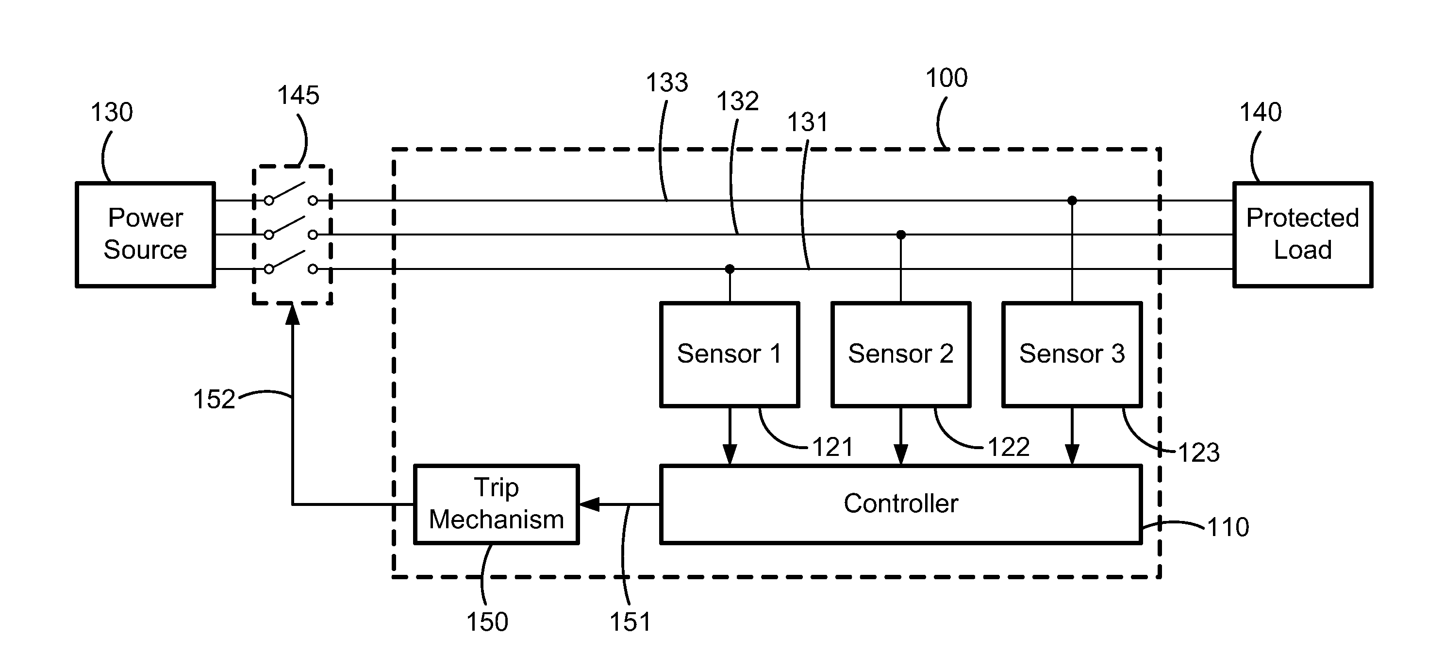
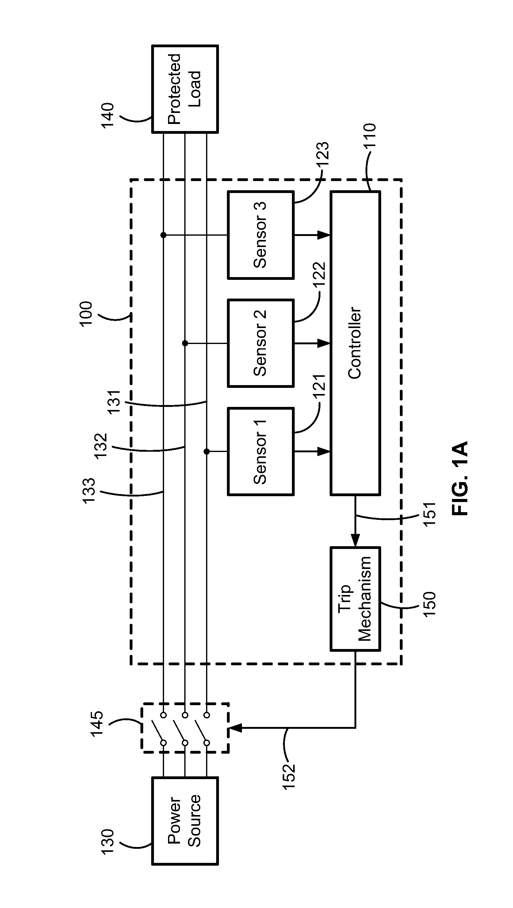
[0013]FIG. 1A is a block diagram of an electronic protection device 100 configured to provide protective functions to a protected load 140 connected to a power source 130. The power source 130 can be a polyphase alternating current (AC) power source. The power source 130 can include three conductive lines 131, 132, 133 for providing three phases of a supply current, and can be arranged according to a delta or wye configuration. In a configuration, the protected load 140 can be an inductive motor load. The electronic protection device 100 includes a first sensor 121, a second sensor 122, a third sensor 123, a controller 110, and a trip mechanism 150. The trip mechanism 150 is configured to receive a trip signal 151 from the controller 110. The three sensors 121, 122, 123 can be configured to provide outputs indicative of an electrical characteristic monitored by the three sensors 121, 122, 123 to the controller 110. For example, the monitored electrical characteristic can be a curren...


PUM


Abstract

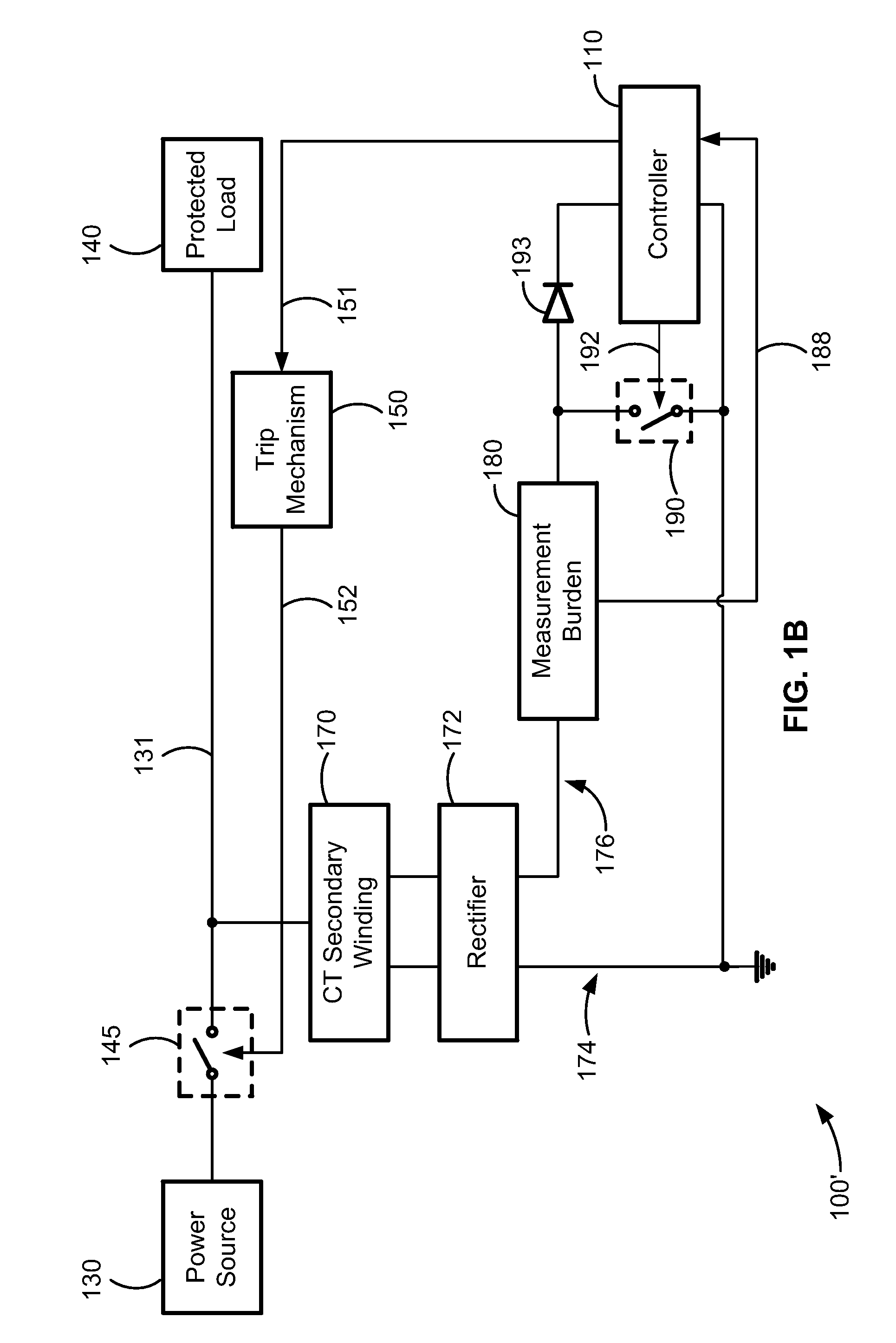
A circuit for measuring current drawn by a self-powered electronic protection device. The circuit monitors current in a polyphase alternating current (AC) power source by measuring current in a rectified secondary winding of a current transformer coupled to a phase current of the power source. The measurement circuit includes a measurement burden connected between the cathode of the current transformer rectifier and a switch. Closing the switch references the voltage drop across the measurement burden to a reference potential. A controller closes the switch while receiving measurements of the voltage drop. Because the voltage drop is referenced to a reference potential, it can be analyzed in a controller to detect a fault condition without being conditioned with an inverting amplifier or a difference amplifier.

Description

FIELD OF THE INVENTION[0001]The present disclosure relates generally to electronic protection devices, and, more particularly, to a configuration for taking measurements in a self-powered electronic protection device.BACKGROUND[0002]Loads connected to electrical circuits can be damaged if the loads draw more current than they are configured to tolerate. For example, inductive motor loads that draw too much current from a power source can suffer from overheating, which degrades the motor life and can potentially break down the insulation in the motor windings. Additionally three-phase inductive motor loads configured to receive power from a three-phase AC power source can be damaged if the power source suffers from a phase loss or phase imbalance. A phase loss occurs when one phase of the current delivered by a polyphase power source is disconnected. A phase loss fault can occur due to a blown fuse or a discontinuous power wire in series with the conductor carrying the phase. A phase...

Claims


Application Information

Patent Timeline
Patent Type & Authority Applications(United States)
IPC IPC(8): G01R1/30G01R23/20G01R15/18
CPCG01R15/183H02H3/083H02H1/063
Inventor JEFFERIES, KEVIN
Owner SCHNEIDER ELECTRIC USA INC
Learn More