
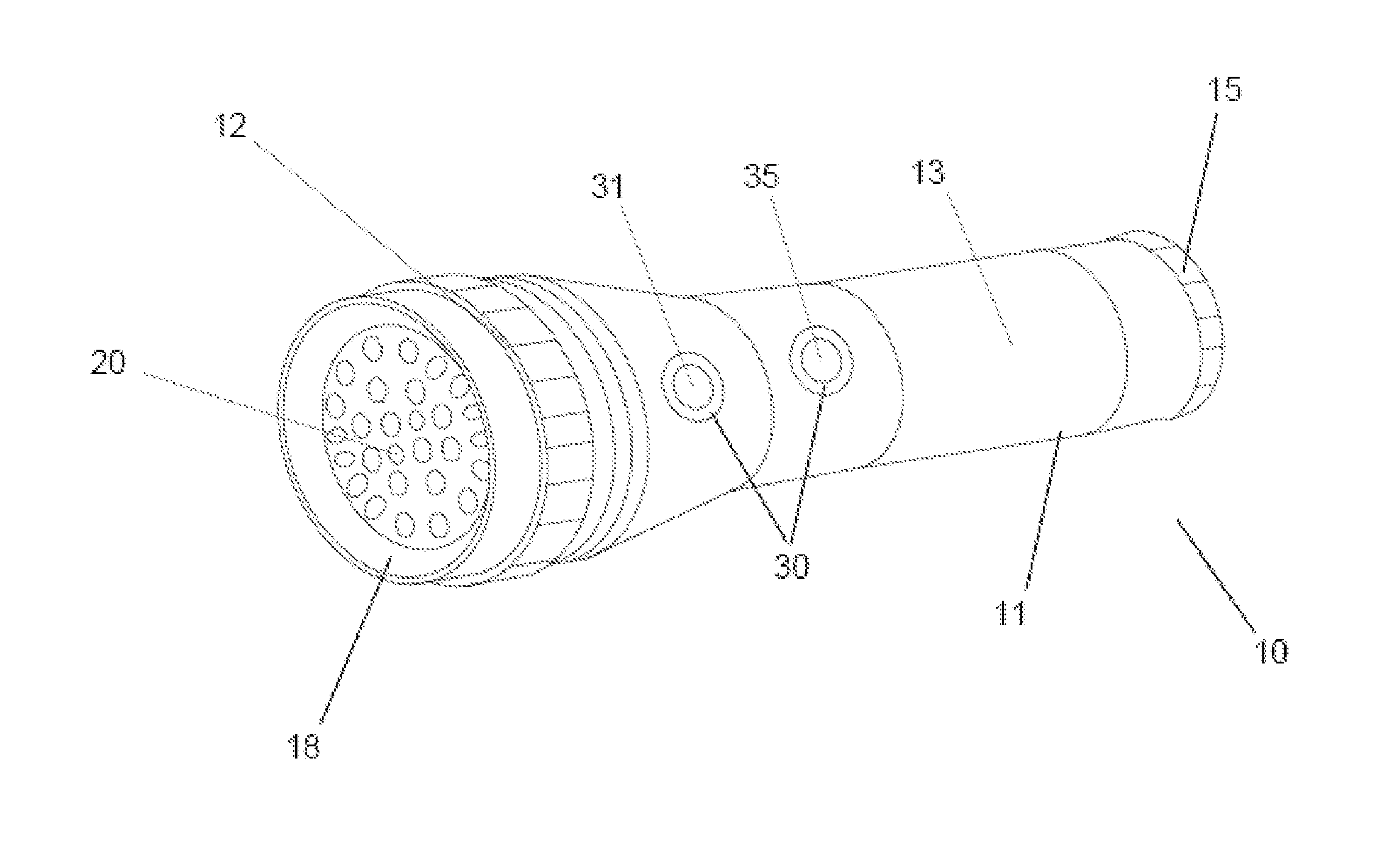
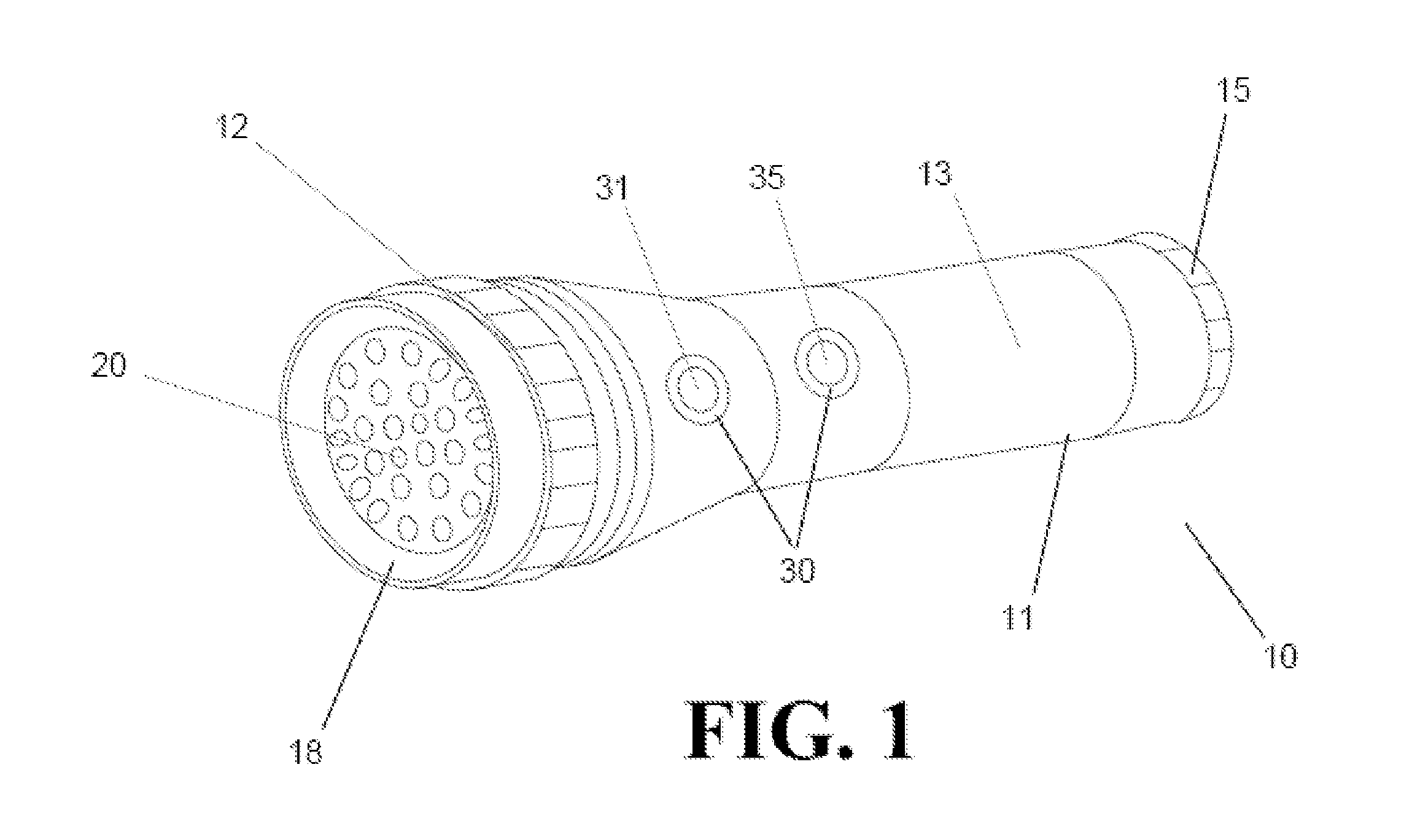
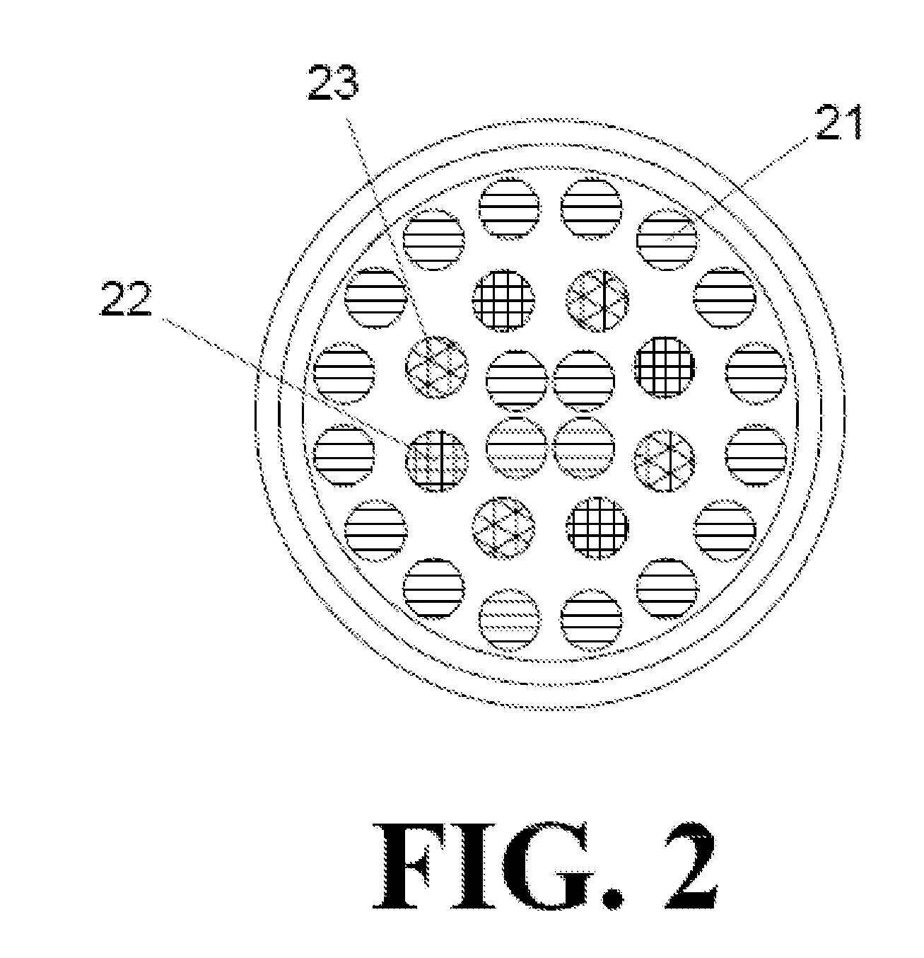
Multimode Flashlight Having Light Emitting Diodes

a light-emitting diode and flashlight technology, applied in the field of hand-held flashlights, can solve the problems of short operating life, high power consumption, and leds usually fail by dimming, and achieve the effect of reducing the number of leds

Active Publication Date: 2012-07-12
AOB PROD CO
View PDF1 Cites 28 Cited by
  • Summary
  • Abstract
  • Description
  • Claims
  • Application Information

AI Technical Summary

Benefits of technology

[0018]Thus, the present invention provides a hand-held flashlight operable for emitting at least two colors, including preferably white, while completely isolating control of the white light from the other colors.

Problems solved by technology

Conventional flashlights use relatively fragile incandescent lamps with a short operating life and high power consumption.
LEDs produce more intense light per watt than do incandescent bulbs, which is useful in the technology of a flashlight that requires long-term usage and whose failure carries serious consequences.
Additionally, LEDs usually fail by dimming over time, providing some warning of their impending failure to the user.
LEDs are solid-state, which makes it much more difficult to break them or make them unusable through accidents like droppage.
However cycling through the white light leads to safety hazards in a number of situations, including aviation, military and police applications, where preserving night vision is necessary; white light is readily picked by and intensified by standard night vision technology.
However, this configuration proves cumbersome, making the flashlight too long and expensive.
While this shortens the length of the flashlight, it results in the operator not knowing which button they are pushing in the dark because the orientation of the flashlight in the operator's hand may not always be known.
Previous technologies do not provide satisfactory solutions.
One would not know which color is being activated, which could accidentally lead to white being activated which may be fatal in, for instance, night military operations.

Method used


Image

  • Multimode Flashlight Having Light Emitting Diodes
  • Multimode Flashlight Having Light Emitting Diodes
  • Multimode Flashlight Having Light Emitting Diodes

Examples


Embodiment Construction

[0028]In the following description, like reference characters designate like or corresponding parts throughout the several views. Also in the following description, it is to be understood that such terms as “forward,”“rearward,”“front,”“back,”“right,”“left,”“upwardly,”“downwardly,” and the like are words of convenience and are not to be construed as limiting terms.

[0029]The present invention provides a flashlight including a body, the body having an exterior surface(s) and further including an interior; disposed, constructed and confined within it a white light wavelength light source; a first switch disposed on the exterior surface(s) of the body that activates functioning of the white light source to a constant on or momentary on; and a second switch disposed on the exterior surface(s) of the body that asynchronously cycles through the functions of the white light source. In preferred embodiments, the second switch functions are selected from the group consisting of blinking, stro...


PUM


Abstract

A flashlight with light emitting diode (LED) sources that produce at least two different colors and at least two other activatable components. The colored LEDs and activatable components cycle on and off using two or three separate switches. One switch cycles preferably white LEDs on and off. Another switch preferably cycles between a non-white LEDs and two other activatable components and combinations thereof. The activatable components include strobes, sirens, GPS tracking, emergency calling, radio, weather notification, laser light, and light not visible to humans. A third switch disposed on the exterior surface(s) of the body that is operable to asynchronously cycle through the functions of the white light source, wherein the functions include blinking, strobe, pre-programmed varying visible intensity, and Morse code messages.

Description

CROSS-REFERENCE TO RELATED APPLICATION[0001]This non-provisional utility patent application is a continuation-in-part of U.S. application Ser. No. 12 / 987,233, filed on Jan. 10, 2011.BACKGROUND OF THE INVENTION[0002]1. Field of the Invention[0003]The present invention relates generally to hand-held flashlights and more specifically to flashlights emitting multiple colors produced by light emitting diodes (LEDs).[0004]2. Description of the Prior Art[0005]Light emitting diodes (LEDs) have provided significant advances in portable light sources, such as flashlights. Conventional flashlights use relatively fragile incandescent lamps with a short operating life and high power consumption. In the 1950s and 1960s, the first widespread reports were published of infrared emission from a semiconductor alloy when provided with electric current, see, e.g., U.S. Pat. No. 3,293,513, to Texas Instruments, Inc., titled “Semiconductor radiant diode”. LEDs are able to emit a certain wavelength of ligh...

Claims


Application Information

Patent Timeline
Patent Type & Authority Applications(United States)
IPC IPC(8): F21L4/02
CPCF21L4/027F21V23/0414F21V23/0421F21L4/02F21Y2101/02F21Y2113/005F21Y2113/02F21V23/0428F21Y2113/13F21Y2113/20F21Y2115/10
Inventor GROSS, BARBARA R.HOLMES, DANNY JOE
Owner AOB PROD CO
Learn More