

Boundary detection device for vehicles
- Summary
- Abstract
- Description
- Claims
- Application Information
AI Technical Summary
Benefits of technology
Problems solved by technology
Method used
Image

Examples
Embodiment Construction
[0034]An embodiment of the present invention will hereinafter be described with reference to the drawings.
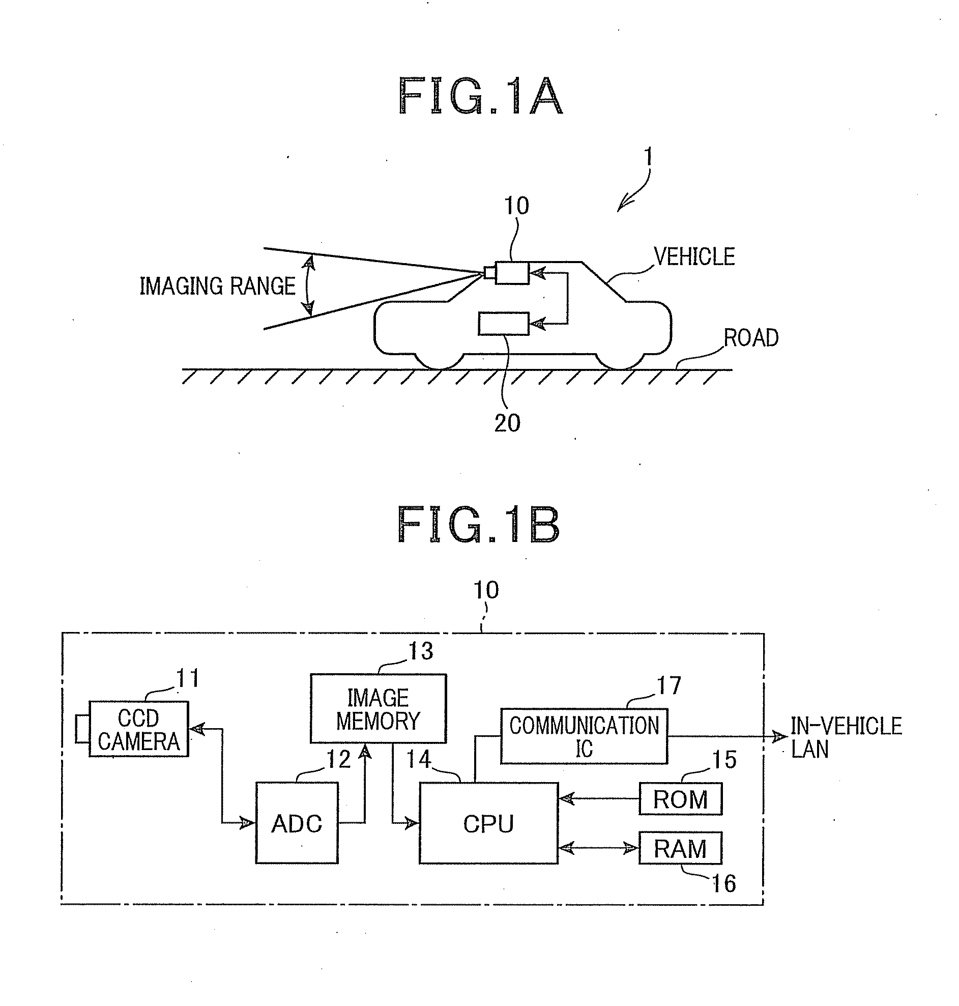
[0035]FIG. 1A and FIG. 1B are block diagrams of a configuration of a boundary detection system 1 that is mounted in a vehicle. FIG. 1A shows an overall configuration. FIG. 1B shows a detailed configuration of a lane boundary detection device that is a main section. As shown in FIG. 1A, the boundary detection system 1 includes a lane boundary detection device 10 (boundary detection device) and a vehicle-control electronic control unit (ECU) 20.
[0036]The lane boundary detection device 10 provides a function for generating boundary parameters indicating a position serving as a boundary (referred to, hereinafter, as a “lane boundary”) of a lane (driving area) in which the own vehicle is traveling. The vehicle-control ECU 20 is connected to the lane boundary detection device 10 by an in-vehicle local area network (LAN). The vehicle-control ECU 20 provides a function for performing va...
PUM
 Abstract
Description
Claims
Application Information