Cable clamp-on device including a user interface

a user interface and cable clamping technology, applied in the field of cable clamping devices, can solve the problems of user confusion, delay and/or call to technical support personnel, and user not familiarity with how to use a particular controller,

Active Publication Date: 2012-07-12
CRESTRON ELECTRONICS
View PDF3 Cites 12 Cited by
  • Summary
  • Abstract
  • Description
  • Claims
  • Application Information

AI Technical Summary

Benefits of technology

[0017]The present invention seeks to overcome or at least ameliorate one or more of several problems, including but not limited to: providing a

Problems solved by technology

In conference room environments, each user's computer can have varied capabilities, which can be problematic when providing information of a specific type to many users.
Often, there are problems associated with both plugging in the cable and using the controller.
Further, the user may not be familiar with how to use a particular controller available in a conference room.
The attempted use of an unfamiliar

Method used


Image

  • Cable clamp-on device including a user interface
  • Cable clamp-on device including a user interface
  • Cable clamp-on device including a user interface

Examples


Embodiment Construction

Mode(s) for Carrying Out the Invention

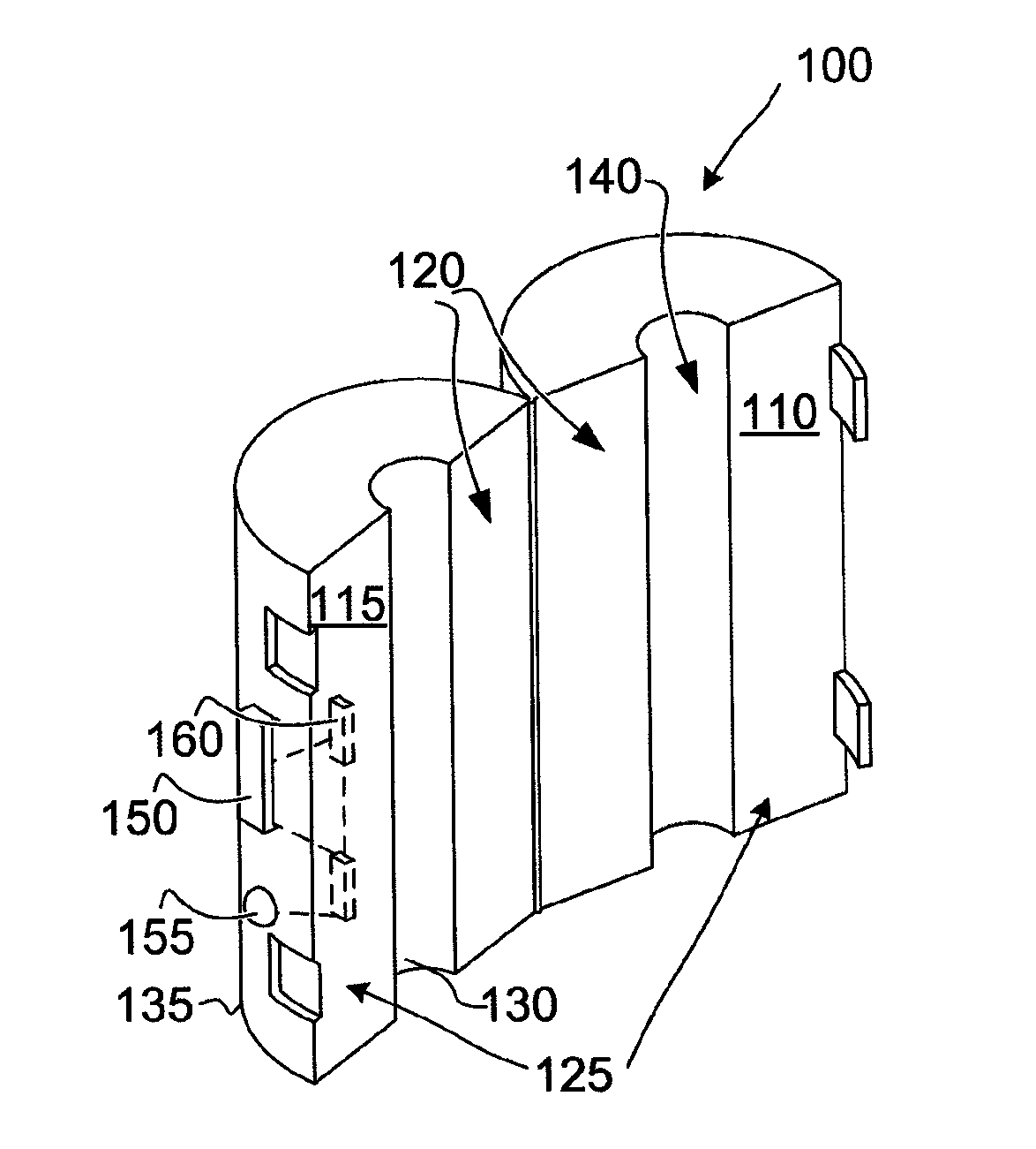
[0127]The present invention relates to a cable clamp-on device for coupling audio / visual devices to a network. More particularly, the invention relates to a cable clamp-on device for communicating audiovisual information to a display system via a wireless communication link in a bidirectional manner.

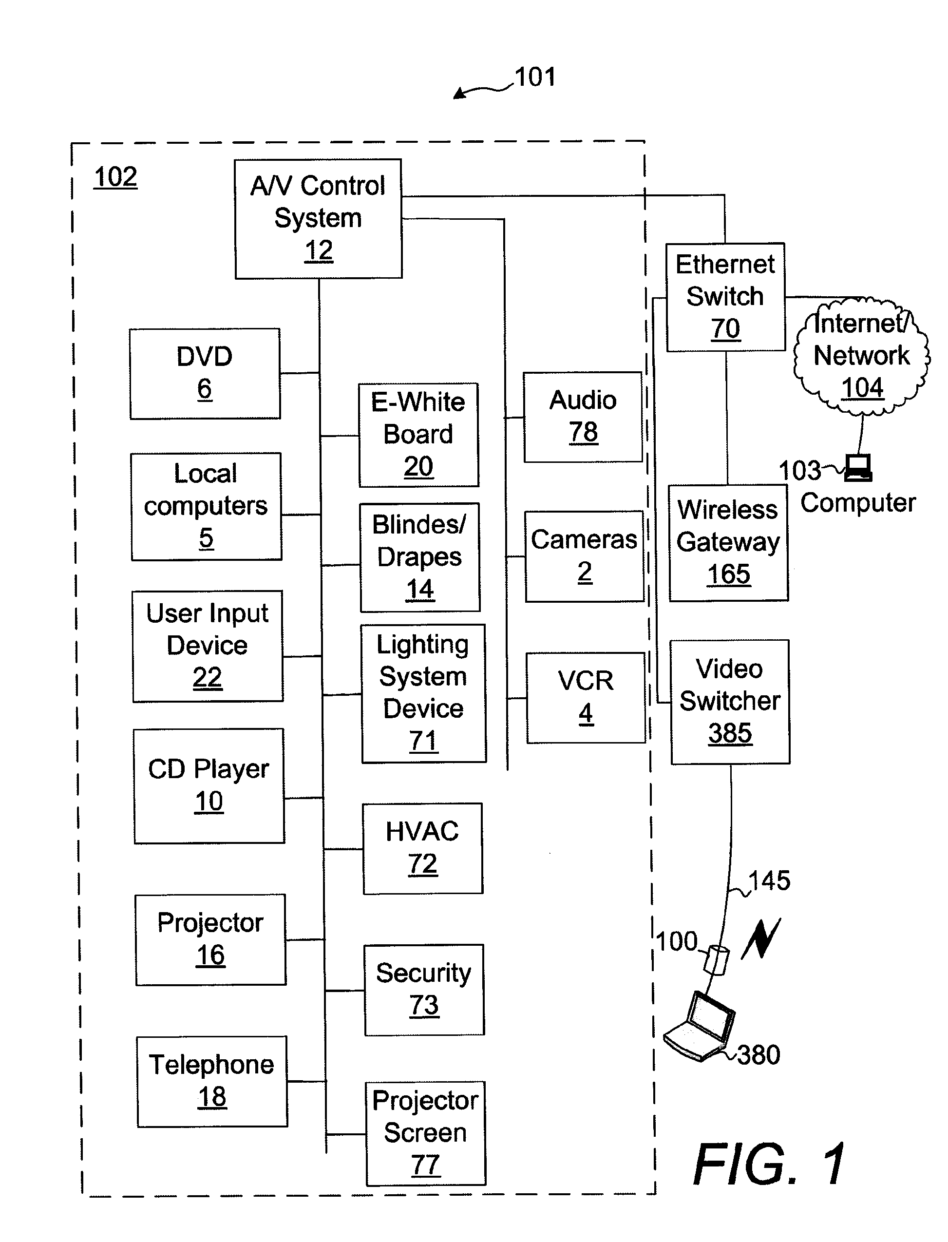
[0128]FIG. 1 is a block diagram illustrating a conference room 101. The conference room 101 includes a plurality of conference room devices 102, which may be remotely controllable using an A / V control system 12. A computer 380 connected via a cable 145 is preferably located within a meeting or conference room 101 to facilitate connection to various conference room devices 102 and / or be an audio / video source. The computer 380 may be a laptop computer. In one embodiment, the computer 380 is directly connected to an audio / video switcher 385 via the cable 145. The audio / video switcher 385 may be a Digital Media Switcher with interface cards that is avail...


PUM


Abstract

In an illustrative embodiment, a cable clamp (100) comprises a first half member (110) and a second half member (115). Each of the half members comprises first and second mating surfaces (120, 125), and interior and exterior surfaces (130, 135). The half members are connected at the first mating surfaces thereof such that the half members form a passageway (140) for receiving a cable (145) therethrough. The clamp further comprises at least one actuator (150) disposed on one of the exterior surfaces, at least one indicator (155) disposed on one of the exterior surfaces, and a transceiver (160) configured to transmit data regarding the at least one actuator and to receive data regarding the indicator via a wireless link.

Description

BACKGROUND OF THE INVENTION[0001]1. Technical Field[0002]The present invention relates to a cable clamp-on device useful for coupling audio / visual devices to a network. More particularly, the invention relates to a cable clamp-on device including a user interface for communicating command / status information with a computer via a wireless communication link in a bidirectional manner.[0003]2. Background Art[0004]As computers become faster and more capable, there are more opportunities to employ various multimedia technologies to enhance presentations. In conference room environments, each user's computer can have varied capabilities, which can be problematic when providing information of a specific type to many users. For example, in a conference room environment, computers are often connected to a wide variety of audio and visual equipment. Often there are cables located near conference room tables for plugging in computers, audio visual (AV) sources, and other conference room device...

Claims


Application Information

Patent Timeline
IPC IPC(8): H04W40/00H02J7/00H04B10/00G09F9/33G08B5/36
CPCH05K9/0066
Inventor FELDSTEIN, GEORGELABOSCO, MARKDRAGONANOVIC, ESTEBANBELLINGHAM, PHILIP
Owner CRESTRON ELECTRONICS
Why Eureka
Try Eureka