
Electrical connector

a technology of electrical connectors and connectors, applied in the direction of coupling contact members, coupling device connections, two-part coupling devices, etc., can solve the problems of plugs, especially those utilized in commercial or industrial environments such as, for example, a construction site, being frequently exposed to rough use, and prongs being frequently damaged

Inactive Publication Date: 2012-07-12
EKCHIAN JACK A
View PDF18 Cites 9 Cited by
  • Summary
  • Abstract
  • Description
  • Claims
  • Application Information

AI Technical Summary

Benefits of technology

[0008]One object of the present invention is to protect exposed, protruding prongs of an electric plug or connector, from being crushed or otherwise damaged, for example, by being stepped on.
[0017]It is a further object of this invention to facilitate the replacement of damaged prongs of an electrical plug so that it may be performed inexpensively and quickly, even by non-electricians.

Problems solved by technology

Plugs, especially those utilized in a commercial or industrial environment such as, for example, a construction site, are frequently exposed to rough usage.
However, when not in use, plugs are frequently left exposed, for example, on the floor of a construction site.
Under such circumstances, the prongs are frequently damaged by forces that cause them to bend and twist.
For example, prongs are frequently crushed when they are stepped on, run over by wheels of various pieces of equipment or hit by, for example, dropped tools or other heavy objects.
They are, therefore, frequently bent and deformed.
Repeated bending and straightening is not only a nuisance, but can be dangerous.
Frequently, metal prongs fatigue and break off after repeated bending.
Even when the plug alone is replaced, it is still an added expense and a nuisance.
Replacement plugs are typically not as rugged or robust as original injection molded plugs.
Also, since they are typically installed by non-electricians, use of replacement plugs increases the risk of causing a short circuit, damaging equipment, and even causing injury or electrocution.
In certain circumstances, especially in the case where only the ground prong breaks off, the plug is used with a missing prong, which increases the likelihood of malfunction, and the danger of electrocution, personal injury or damage to equipment.
Prongs that have been repeatedly bent cannot be fully straightened and as a result frequently do not fit properly in a receptacle and can damage the receptacle as well.

Method used


Image

  • Electrical connector
  • Electrical connector
  • Electrical connector

Examples


Embodiment Construction

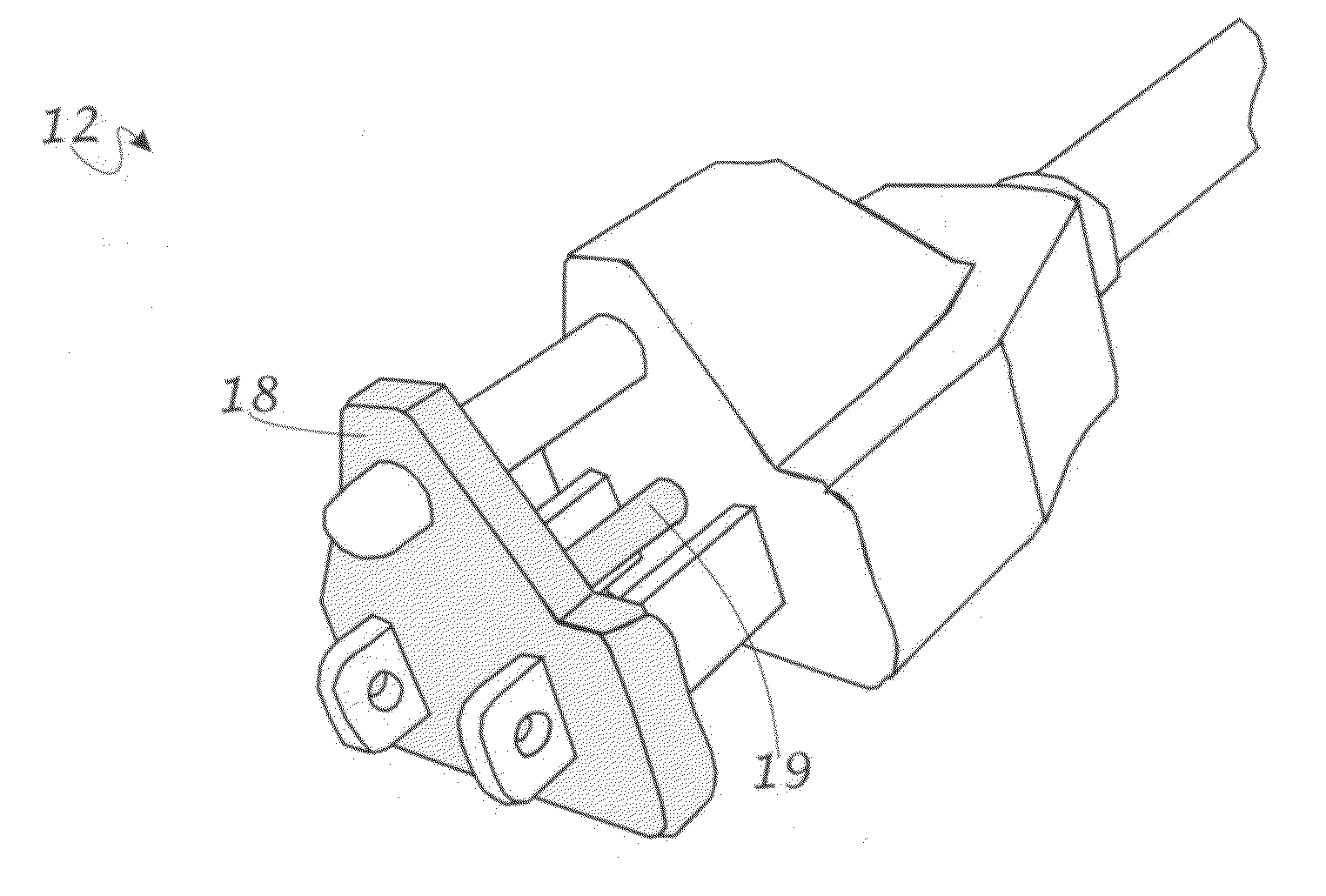
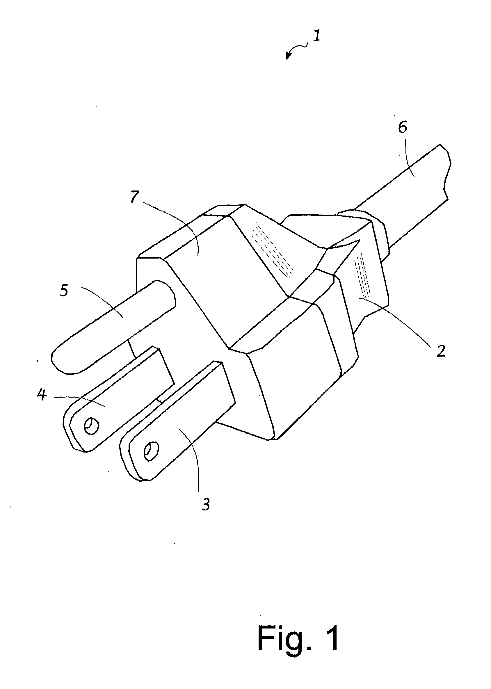
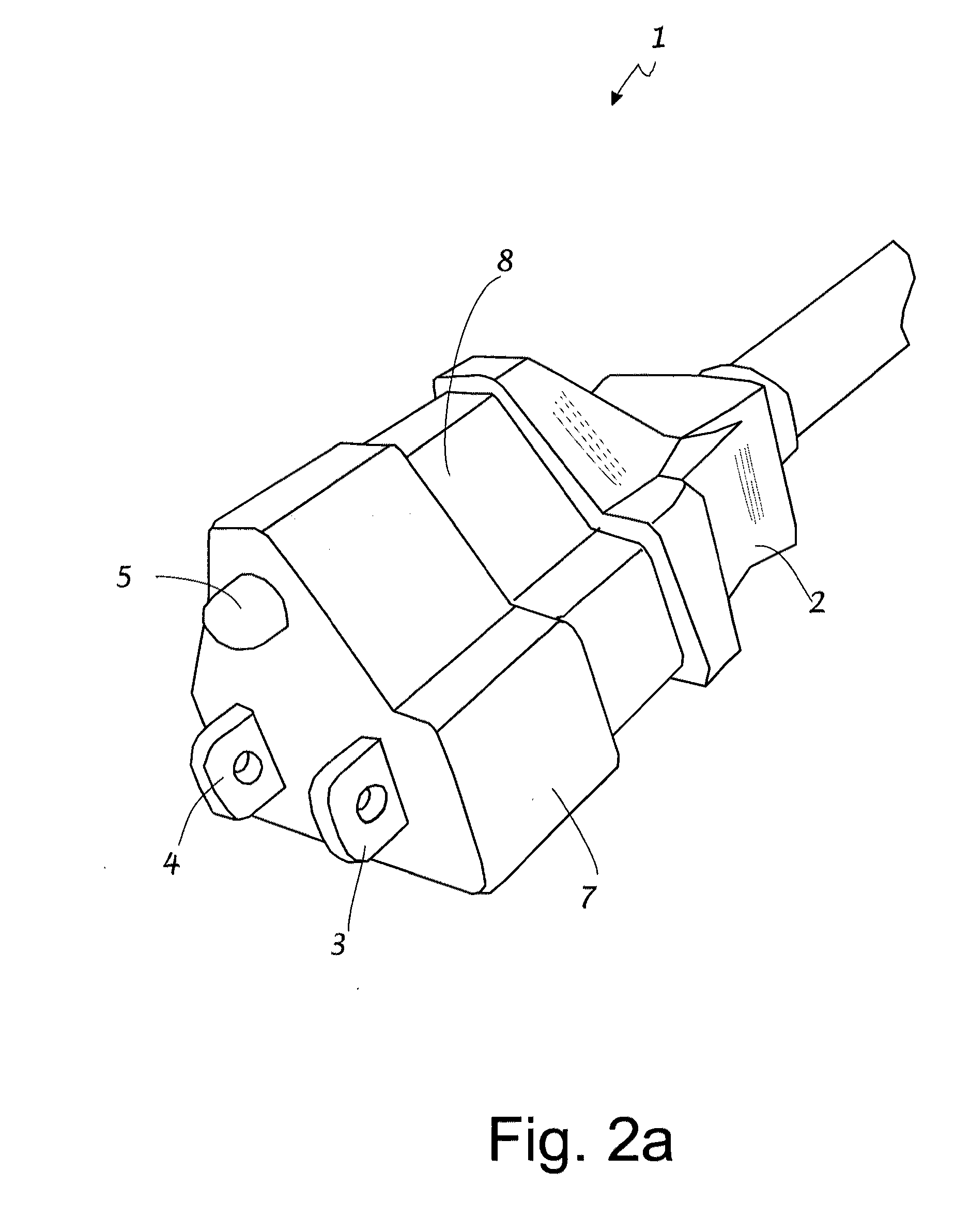
[0065]FIG. 1 shows a schematic of a three prong plug 1, configured according to an embodiment of the invention, comprising plug base 2, prongs 3, 4, and 5, electrical cord 6, and integral brace element 7. Plug 1 may be attached, for example, to one end of a power cord, such as an extension cord or the electric cable of a tool or appliance. Electrically conductive prongs 3, 4 and 5 are connected to three mutually insulated conductors (not shown) within an insulated electric cord or cable 6. The plug base 2 encapsulates the connections between prongs 3, 4, and 5 and the corresponding conductors in the electrical cord 6. Plug base 2 may be fabricated, for example, from a plastic material by injection molding. A plastic plug base may be produced by, for example, using an overmolding or insert molding process. In the case, for example, of a typical NEMA 5-15 plug, prongs 3, 4, and 5 would connect to the hot, neutral and ground terminals respectively when plugged into a matching electric ...


PUM


Abstract

Electric plugs or connectors are provided where protruding prongs are protected or reinforced by a brace element. A brace element is used to buttress the prongs when the plug is not plugged into an electric receptacle. Plugs may be configured such that the brace element is deployed manually or automatically. Plugs may also be configured so that if the prongs are damaged, they can readily be replaced.

Description

CROSS-REFERENCE TO RELATED APPLICATIONS[0001]This application claims priority of US Provisional Patent Applications No. 61 / 460,689, filed Jan. 6, 2011; No. 61 / 574,828, filed Aug. 10, 2011; and No. 61 / 630,000, filed Dec. 2, 2011, which are hereby incorporated herein by reference in their entirety.FIELD OF INVENTION[0002]The present invention generally relates to electrical connectors with protruding prongs that are used to connect to a receptacle that receives the prongs. In particular, it relates to the protection of such prongs from damage or the facilitating of their replacement when damaged.BACKGROUND[0003]Home appliances, power tools, space heaters, and other equipment that consume electric power are ubiquitous in society. In order to operate properly, such devices frequently rely on electrical connectors or plugs to connect to an alternating or direct current source. Such connectors frequently utilize protruding prongs of various shapes and lengths that, in use, are intended to...

Claims


Application Information

Patent Timeline
Patent Type & Authority Applications(United States)
IPC IPC(8): H01R13/04
CPCH01R13/4538H01R2103/00H01R31/06H01R24/30
Inventor EKCHIAN, JACK A.
Owner EKCHIAN JACK A
Learn More