Percutaneous heart pump

Active Publication Date: 2012-07-12
TC1 LLC
View PDF3 Cites 180 Cited by
  • Summary
  • Abstract
  • Description
  • Claims
  • Application Information

AI Technical Summary

Benefits of technology

[0009]In some embodiments, a heart pump is provided comprising an elongate catheter body, an impeller disposed at the distal end of the elongate catheter body, and one or more bearings positioned between the catheter body and the impeller, wherein at least one of the bearings comprises a surface facing a portion of the impeller. The heart pump further includes an inflow channel disposed within the elongate catheter body for directing infusant to the surface of the bearings facing the impeller and an outflow channel for directing infusant away from the surface of the bearings. At least one debris capturing structure is positioned along the outflow channel downstream of the one or more bearings.
[0010]In some embodiments, a heart pump is provided comprising an elongate catheter body; an impeller disposed at the distal end of the elongate catheter body; one or more bearings positioned betwee

Problems solved by technology

Heart disease is a major health problem that claims many lives per year.
Surgical insertion, however, can cause additional serious stresses in heart failure patients.
Conventio

Method used


Image

  • Percutaneous heart pump
  • Percutaneous heart pump
  • Percutaneous heart pump

Examples


Embodiment Construction

[0037]Major components of heart pumps that can be applied percutaneously to a patient are described below in Section I. Section II describes various structures that facilitate the rotatable support of a cantilevered impeller. Section III describes strategies for minimizing a patient's negative reaction to the presence of the systems within the cardiovascular system. Section IV describes various structures that facilitate the capture of debris within the pump. Section V describes an active pump system for maintaining desired flow or pressure. Section VI describes a valve arrangement to expel air and prime the heart pump. Section VII describes various methods and techniques in connection with structures of heart pumps.

I. Overview of Heart Pumps

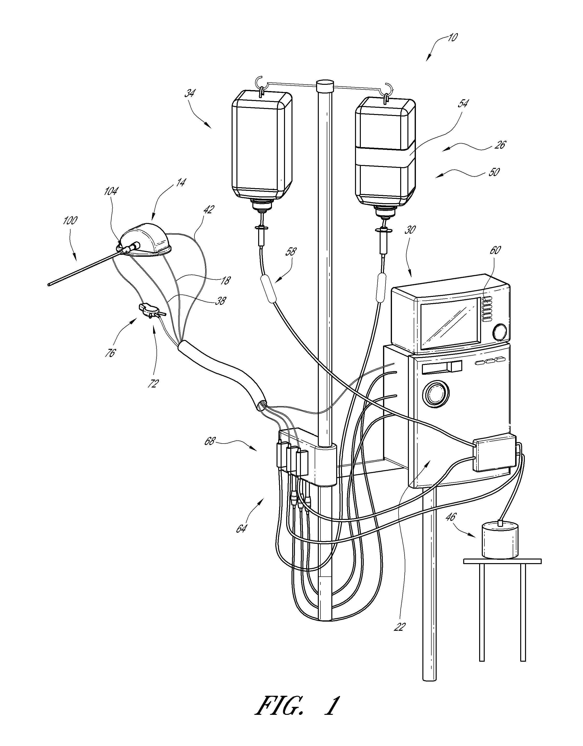
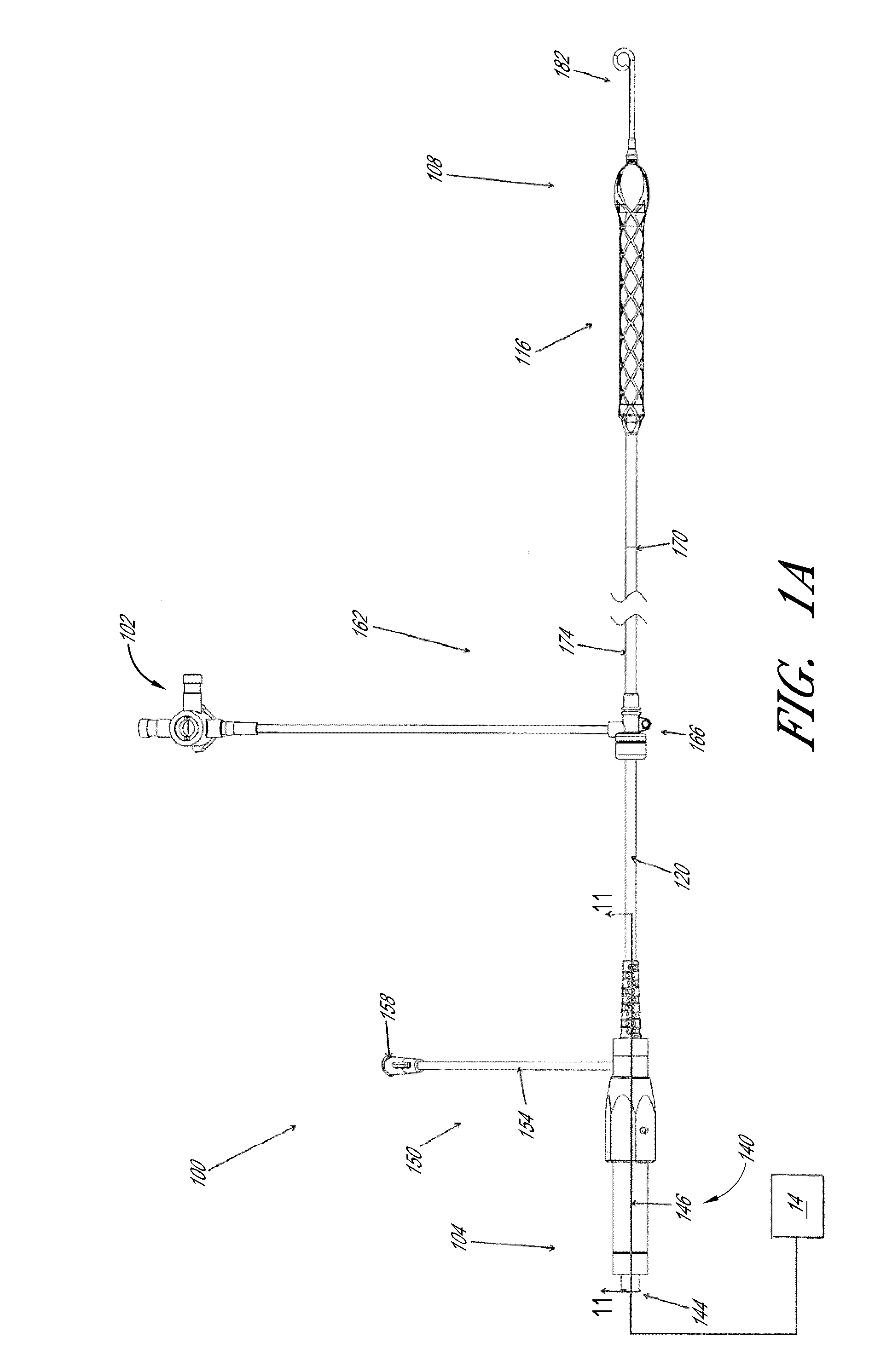
[0038]FIG. 1 illustrates one embodiment of a heart pump 10 that includes a catheter assembly 100 having a proximal end 104 adapted to connect to a motor 14 and a distal end 108 (see FIG. 1A) adapted to be inserted percutaneously into a patient. ...


PUM


Abstract

A heart pump is provided that comprises an elongate catheter body, an impeller disposed at the distal end of the elongate catheter body, and one or more bearings positioned between the catheter body and the impeller. A fluid supply line for delivering infusant into the catheter is provided. A fluid return line for transporting infusant out of the catheter is also provided. A pump assembly for regulating the infusant flow along the fluid supply line and fluid return line is provided as part of an infusion system.

Description

CROSS-REFERENCE TO RELATED APPLICATIONS[0001]This application claims priority to U.S. Provisional Application Ser. No. 61 / 430,171 filed Jan. 6, 2011 entitled Percutaneous Heart Pump, and U.S. Provisional Application Ser. No. 61 / 430,517 filed Jan. 6, 2011 entitled Percutaneous Heart Pump, both of which are hereby incorporated by reference herein for all purposes.BACKGROUND OF THE INVENTION[0002]1. Field of the Invention[0003]This application is directed to heart pumps that can be applied percutaneously.[0004]2. Description of the Related Art[0005]Heart disease is a major health problem that claims many lives per year. After a heart attack, only a small number of patients can be treated with medicines or other non-invasive treatment. However, a significant number of patients can recover from a heart attack or cardiogenic shock if provided with mechanical circulatory support.[0006]In a conventional approach, a blood pump having a fixed cross-section is surgically inserted a heart chamb...

Claims


Application Information

Patent Timeline
IPC IPC(8): A61M1/12
CPCA61M1/101A61M25/04A61M1/125A61M1/122A61M1/1024A61M60/824A61M60/829A61M60/414A61M60/148A61M60/808A61M60/554A61M60/865A61M60/237A61M60/13A61M60/538A61M60/825
Inventor WALTERS, DANIEL A.REPKA, WILLIAM JAMESPRAIS, BRIAN A.WILLIAMS, JONATHAN R.
Owner TC1 LLC
Why Eureka
Try Eureka