Motion analysis device and motion analysis method

a technology of motion analysis and analysis method, which is applied in the direction of material strength using steady bending force, instruments, gymnastics, etc., can solve the problems of time from measurement, detection sensitivity of angular velocity, and difficulty in measuring deformation amount, so as to achieve accurate calculation and high accuracy

Active Publication Date: 2012-07-12
SEIKO EPSON CORP
View PDF18 Cites 80 Cited by
  • Summary
  • Abstract
  • Description
  • Claims
  • Application Information

AI Technical Summary

Benefits of technology

[0023]The motion analysis method of this configuration uses the fact that the difference is caused between the posture angles detected by two posture angle sensors in accordance with the error in the installation angles of the two posture angle sensors, and corrects the difference in the angular velocity between the two points of the measurement object in accordance with the difference in the posture angle between the two points. Further, since the variation of the difference in the posture angle between the two points can accurately be calculated by integrating the difference between the angular velocities after the correction, the deformation amount between the two points can be analyzed with high accuracy.

Problems solved by technology

However, since the image is analyzed in this method, there is a disadvantage that it is difficult to measure the deformation amount due to the deflection and the torsion with high accuracy, and further, it takes time from the measurement until the actual data is obtained.
However, according to this method, since the error in the installation angle of the gyro sensor attached to the grip portion and the installation angle of the gyro sensor attached to the head portion causes the error in the detection sensitivity of the angular velocity, it is required to accurately conform the installation angles to each other.
However, since the grip portion and the head portion are distant roughly 1 m from each other, it is extremely difficult to accurately conform the installation angles of the two gyro sensors to each other.
However, it is also extremely difficult to accurately measure the error in the installation angle.

Method used


Image

  • Motion analysis device and motion analysis method
  • Motion analysis device and motion analysis method
  • Motion analysis device and motion analysis method

Examples


first embodiment

1. First Embodiment

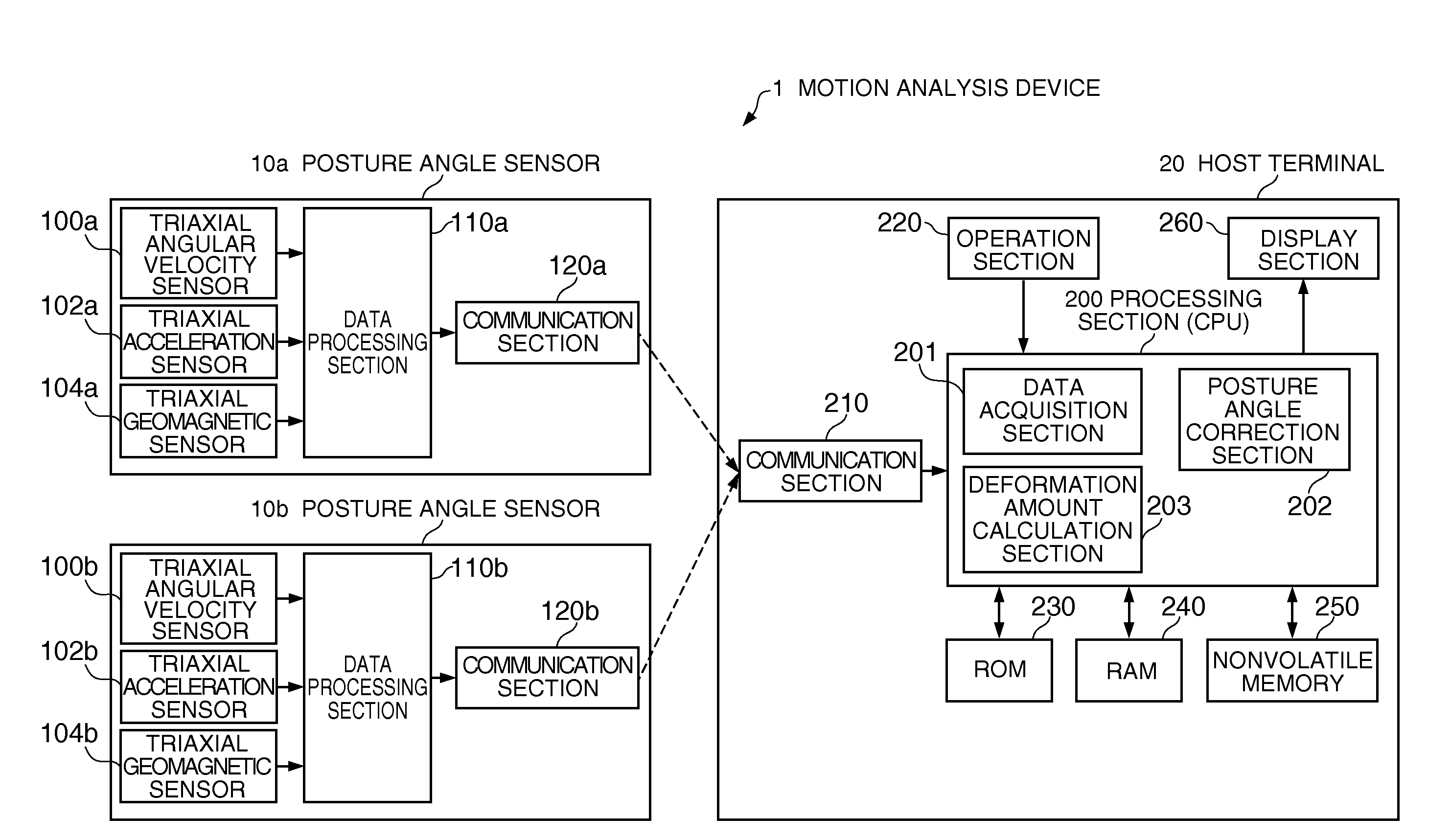
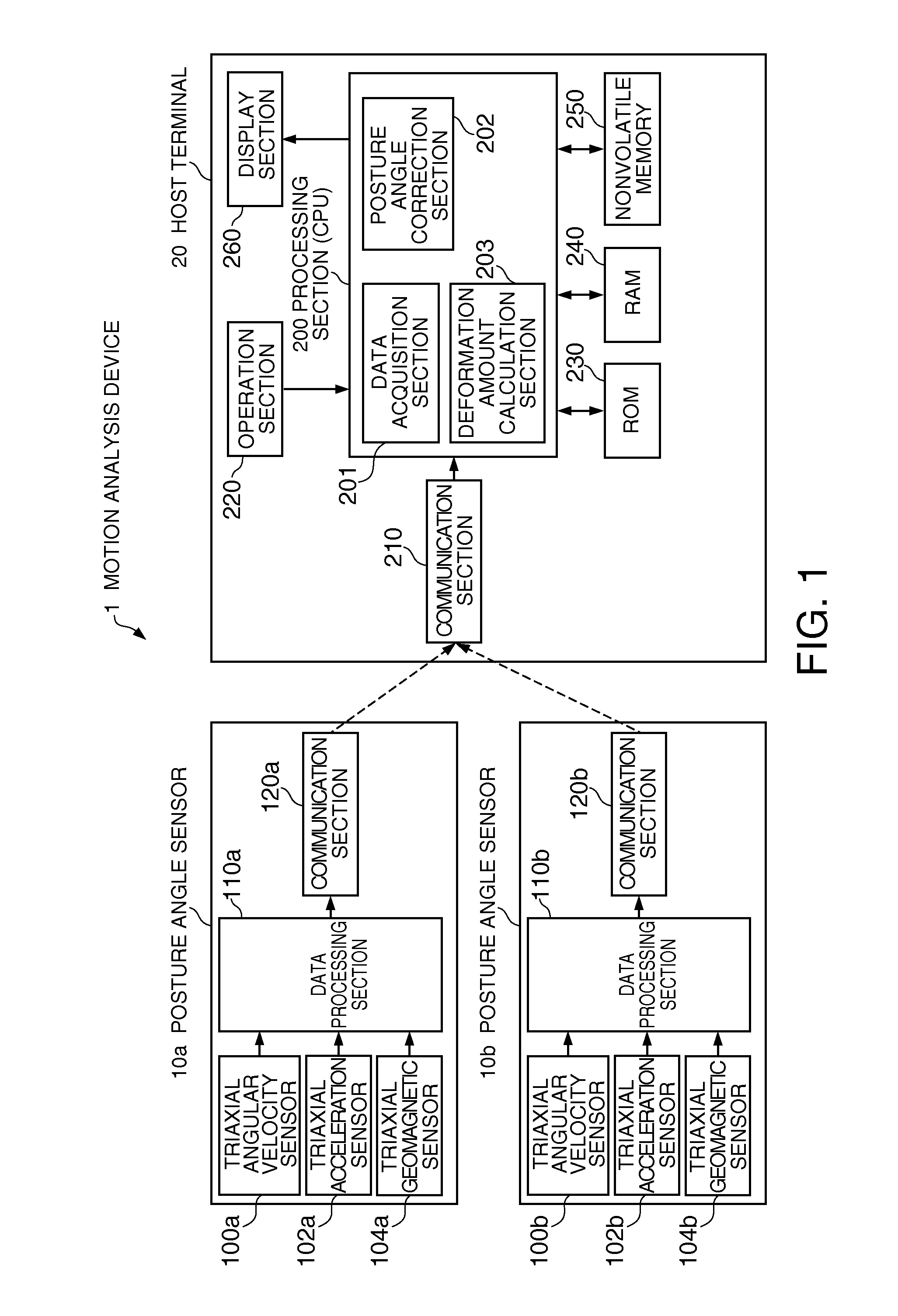
[0037]FIG. 1 is a diagram showing a configuration of a motion analysis device according to a first embodiment. The motion analysis device 1 according to the present embodiment is configured including two posture angle sensors 10a, 10b, and a host terminal 20. The posture angle sensors 10a, 10b and the host terminal 20 are connected to each other in a wired or wireless manner. The posture angle sensors 10a, 10b are attached to a measurement object to be the object of the motion analysis at respective locations distant from each other.

[0038]The posture angle sensor 10a includes, for example, a triaxial angular velocity sensor 100a, a triaxial acceleration sensor 102a, a triaxial geomagnetic sensor 104a, a data processing section 110a, and a communication section 120a.

[0039]The triaxial angular velocity sensor 100a detects the angular velocities around three axes (an x1 axis, a y1 axis, and a z1 axis) perpendicular to each other, and then outputs a signal (triaxial ...

second embodiment

2. Second Embodiment

[0082]FIG. 9 is a diagram showing a configuration of a motion analysis device according to a second embodiment. In the motion analysis device according to the second embodiment, the posture angle sensor 10a transmits the angular velocity data (ωx1, ωy1, ωz1) around the three axes, namely the x1 axis, the y1 axis, and the z1 axis, to the host terminal 20 at a constant period in addition to the posture angle data in the XYZ coordinate system. Further, the posture angle sensor 10b also transmits the angular velocity data (ωx2, ωy2, ωz2) around the three axes, namely the x2 axis, the y2 axis, and the z2 axis, to the host terminal 20 at a constant period in addition to the posture angle data in the XYZ coordinate system. It should be noted that the posture angle sensors 10a, 10b are not necessarily required to output the angular velocity data around the three axes, but are required to output the angular velocity data around the axes necessary for the analysis.

[0083]Fu...

specific example

[0093]Then, the method according to the second embodiment will be explained citing an example of calculating the deformation amounts (a deflection amount and a torsion amount) of a golf club in a swing of the golf club similarly to the first embodiment. Similarly to the case explained in the first embodiment, also in this example, the golf club corresponds to the measurement object, the posture angle sensor 10a and the posture angle sensor 10b are attached to the golf club at the locations distant from each other, and the motion analysis device 1 functions as a golf swing analysis device.

[0094]In particular, the angular velocity correction section 204 calculates the difference in the posture angle between the posture angle sensors 10a, 10b every period Δt, and corrects (converts) the triaxial angular velocities ωx2, ωy2, and ωz2 acquired from the posture angle sensor 10b respectively to the angular velocities ωx2′, ωy2′, and ωz2′ around the three axes, namely the x1 axis, the y1 axi...


PUM


Abstract

A motion analysis device includes two posture angle sensors attached to a measurement object at locations distant from each other, a data acquisition section, a posture angle correction section, and a deformation amount calculation section. The data acquisition section acquires data of a first posture angle and a second posture angle respectively detected by the posture angle sensors. The posture angle correction section corrects a difference between the first posture angle and the second posture angle after starting a motion of the measurement object in accordance with a difference between the first posture angle and the second posture angle before starting the motion of the measurement object. The deformation amount calculation section calculates a deformation amount of the measurement object based on a difference between the first posture angle and the second posture angle corrected by the posture angle correction section.

Description

BACKGROUND[0001]1. Technical Field[0002]The present invention relates to a motion analysis device and a motion analysis method.[0003]2. Related Art[0004]In the characteristic evaluation of a golf club, analysis of the deflection and the torsion thereof when making a swing is performed. In the past, there has been known a method of shooting the behavior of a golf club when making a swing with a camera, and then analyzing the deflection and the torsion of the golf club based on the shot image. However, since the image is analyzed in this method, there is a disadvantage that it is difficult to measure the deformation amount due to the deflection and the torsion with high accuracy, and further, it takes time from the measurement until the actual data is obtained.[0005]On the other hand, in JP-A-2008-73210, there is proposed a method of attaching gyro sensors respectively to a head portion and a grip portion of a golf club to thereby evaluate the head speed of a swing, the carry, and so ...

Claims


Application Information

Patent Timeline
Patent Type & Authority Applications(United States)
IPC IPC(8): G06F15/00
CPCA63B2220/40A63B69/36A63B69/3611A63B2225/50A63B2220/34A63B2220/833A63B24/0003G01B21/22G01N3/20G01N3/22G01P3/00
Inventor TAKASUGI, TOSHIYASUSATO, MASATOSHINOMURA, KAZUO
Owner SEIKO EPSON CORP
Why Eureka
Try Eureka