Folding knife

a folding knife and blade technology, applied in the field of folding knives, can solve the problems of user's ability to resist the force of the locking arm, fail to press against the blade, and the user is very likely to be accidentally cut by the blade, so as to achieve enhanced stability and safety. the effect of us

Inactive Publication Date: 2012-07-19
LO YEN FEN
View PDF19 Cites 22 Cited by
  • Summary
  • Abstract
  • Description
  • Claims
  • Application Information

AI Technical Summary

Benefits of technology

[0007]In view of the fact that the resilient locking arm of the conventional folding knife has insufficient structural strength and is hence responsible for accidental folding of the blade and potential cutting injury, the inventor of the present invention put years of practical experience into research and experiment and, after repeated trials and tests, finally succeeded in developing a folding knife as disclosed herein. The disclosed folding knife is intended to provide enhanced stability and safety is use.
[0009]It is another object of the present invention to provide the foregoing folding knife, wherein the third panel is formed with a groove corresponding in configuration to the positioning plate. Thus, not only can the positioning plate be moved along the groove in the longitudinal direction of the resilient locking arm, but also the second engaging portion can be moved precisely into engagement with the first engaging portion while the positioning plate is pushed toward the first end of the resilient locking arm, so as for the blade to be received in the handle. Besides, during assembly of the folding knife, the positioning plate can be positioned for operation simply by placing it into the groove, thus simplifying and shortening the assembly process of the folding knife. Furthermore, in order for the restoring spring to push the positioning plate, the restoring spring only needs to be positioned in such a way that it is pressed against the second end of the positioning plate; in other words, it is not necessary to place the restoring spring precisely against the second engaging portion. Therefore, when the folding knife is impacted by an external force, the positioning plate will not experience difficulty in movement simply because the restoring spring is slightly shifted in position. In a nutshell, the durability of the folding knife is enhanced.

Problems solved by technology

However, as the resilient locking arm is installed in the handle in a movable manner, the aforesaid end of the resilient locking arm may deform and therefore fail to press against the blade when the blade is subjected to an excessively large force.
Should it happen, the user is very likely to be accidentally cut by the blade.
(1) A complicated overall structure and an elaborate assembly process: During assembly of the folding knife 1, the pushing element 151 must be mounted around the pivot 110 before the first end of the restoring spring 152 is positioned in the first end of the receiving groove 133a. Afterward, the restoring spring 152 must be wound around the post 133b such that the second end of the restoring spring 152 is pressed against the projection 151a. This assembly process is far more complicated than that of the conventional folding knife and demands absolute concentration and patience from the assembly operator. In consequence, the folding knife 1 is very likely to be manufactured at low efficiency and high cost.
(2) Insecureness of the pushing device 15: As the restoring spring 152 is positioned in the receiving groove 133a by winding around the post 133b, the second end of the restoring spring 152 must be placed precisely against the projection 151a in order to bias the pushing element 151. However, when the folding knife 1 is subjected to an external impact, the restoring spring 152 tends to loosen or be shifted in position such that the second end thereof no longer presses against the projection 151a, or that the pushing device 15 becomes less responsive to the user's operation. Since durability has always been an important feature expected of folding knives, the aforesaid drawback of the folding knife 1 is highly undesirable.
Moreover, manufacture efficiency and product durability may be compromised when the pushing device 15 is impacted and loosened; in other words, the folding knife 1 does not provide a sound solution to improving the instability of the conventional folding knife during use.

Method used


Image

  • Folding knife
  • Folding knife
  • Folding knife

Examples


Embodiment Construction

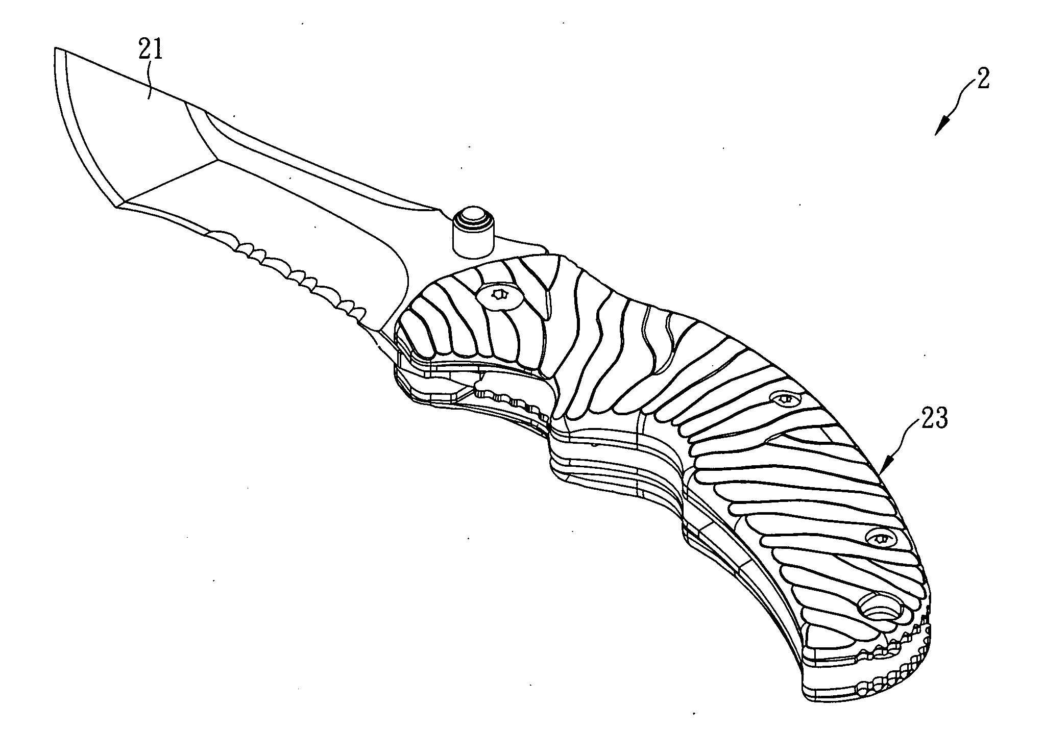
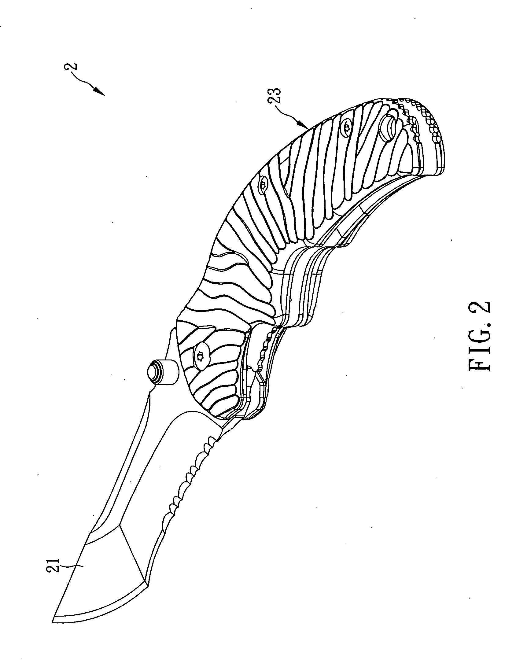
[0015]The present invention provides a folding knife. Referring to FIG. 2 and FIG. 3 for a preferred embodiment of the present invention, the folding knife 2 includes a blade 21, a handle 23, and a positioning plate 25. A portion of the blade 21 that is adjacent to a first end thereof is pivotally connected in the handle 23 by a pivot 210. A second end of the blade 21 is pivotable about the pivot 210 and can be rotated out of the handle 23 from a first side thereof or be rotated into and received in the handle 23. The handle 23 is composed at least of a first panel 231, a second panel 233, and a third panel 235. The aforesaid portion of the blade 21 that is adjacent to the first end thereof is positioned between the first panel 231 and the second panel 233 by the pivot 210. The second panel 233 is provided with a post 20 and a resilient locking arm 233a. The post 20 is adjacent to one end of the second panel 233 so as to press against the first end of the blade 21 when the blade 21 ...


PUM


Abstract

The present invention is to provide a folding knife having a blade pivotally connected to a handle. A resilient locking arm has a first end fixed inside to the handle and a second end extending slantingly toward the blade when the blade is received in the handle. A positioning plate is movably positioned in the handle, and has a first end extending outside to the handle. Once the blade is received in the handle, the positioning plate engages with the resilient locking arm. However, when the blade is rotated out of the handle completely, the second end of the resilient locking arm presses against the end of the blade in a locked position, and thereby the positioning plate disengages with the resilient locking arm and presses against the resilient locking arm to avoid the blade from being out of the locked position and rotated into the handle.

Description

FIELD OF THE INVENTION[0001]The present invention relates a folding knife, more particularly to a folding knife having a positioning plate movably positioned in a handle thereof, wherein the positioning plate engages with a resilient locking arm inside the handle when the blade is received in the handle. However, when the blade is rotated out of the handle completely, an end of the resilient locking arm presses against the end of the blade in a locked position, and thereby the positioning plate disengages with the resilient locking arm and presses against the resilient locking arm to avoid the blade from being out of the locked position and rotated into the handleBACKGROUND OF THE INVENTION[0002]Recently, with the advancement of craft techniques and the improvement of living standards, people who intend to buy a new product consider not only the price and durability of the product, but also whether the product is convenient and safe to use. Such a change in market trends has driven ...

Claims


Application Information

Patent Timeline
Patent Type & Authority Applications(United States)
IPC IPC(8): B26B3/06
CPCB26B1/044
Inventor LO, YEN-FEN
Owner LO YEN FEN
Why Eureka
Try Eureka